Thank you for purchasing the ADTR Coil Over Suspension system for your 92-02 Crown Victoria, Grand Marquis and Town Car. Below you’ll see some helpful information and pictures for installation.
Front:
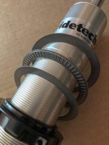
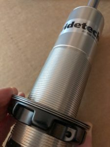
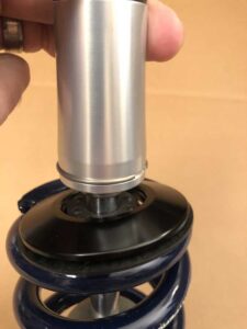
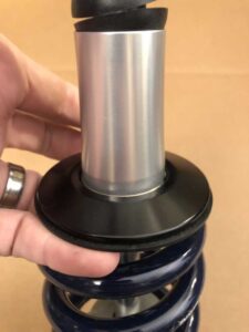
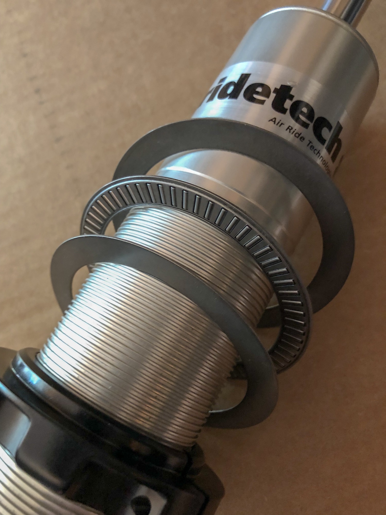
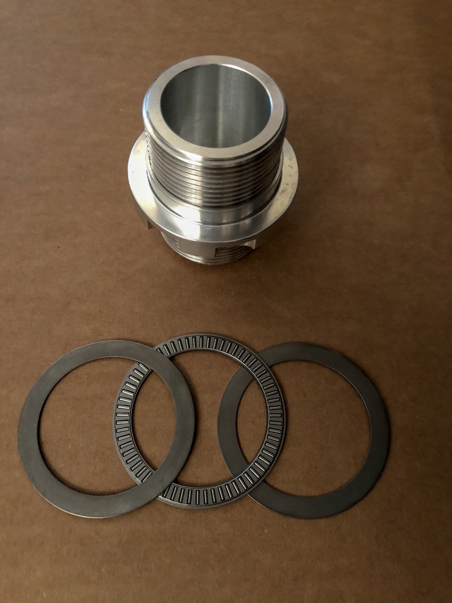
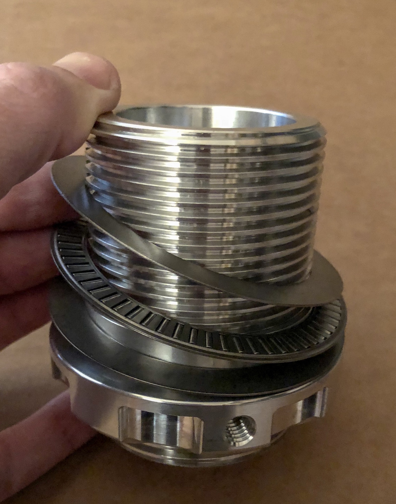
- The front part of our system uses Ridetech HQ series coil over shocks. Start with assembling the units. We suggest using the supplied QA1 thrust bearings on the bottom spring perch. The orientation of the thrust bearings is as follows: washer / thrust bearing / washer and that goes on the bottom spring perch. Apply some general purpose grease to help them stay lubricated. Install the Delrin spring washer on the upper spring perch. See attached pics for reference:

- The front spring we use in our standard kit is an 8″ 850# rate spring. When unboxing everything just make sure you don’t mix up the front springs with the rear springs.
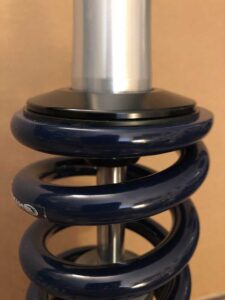
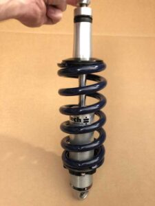
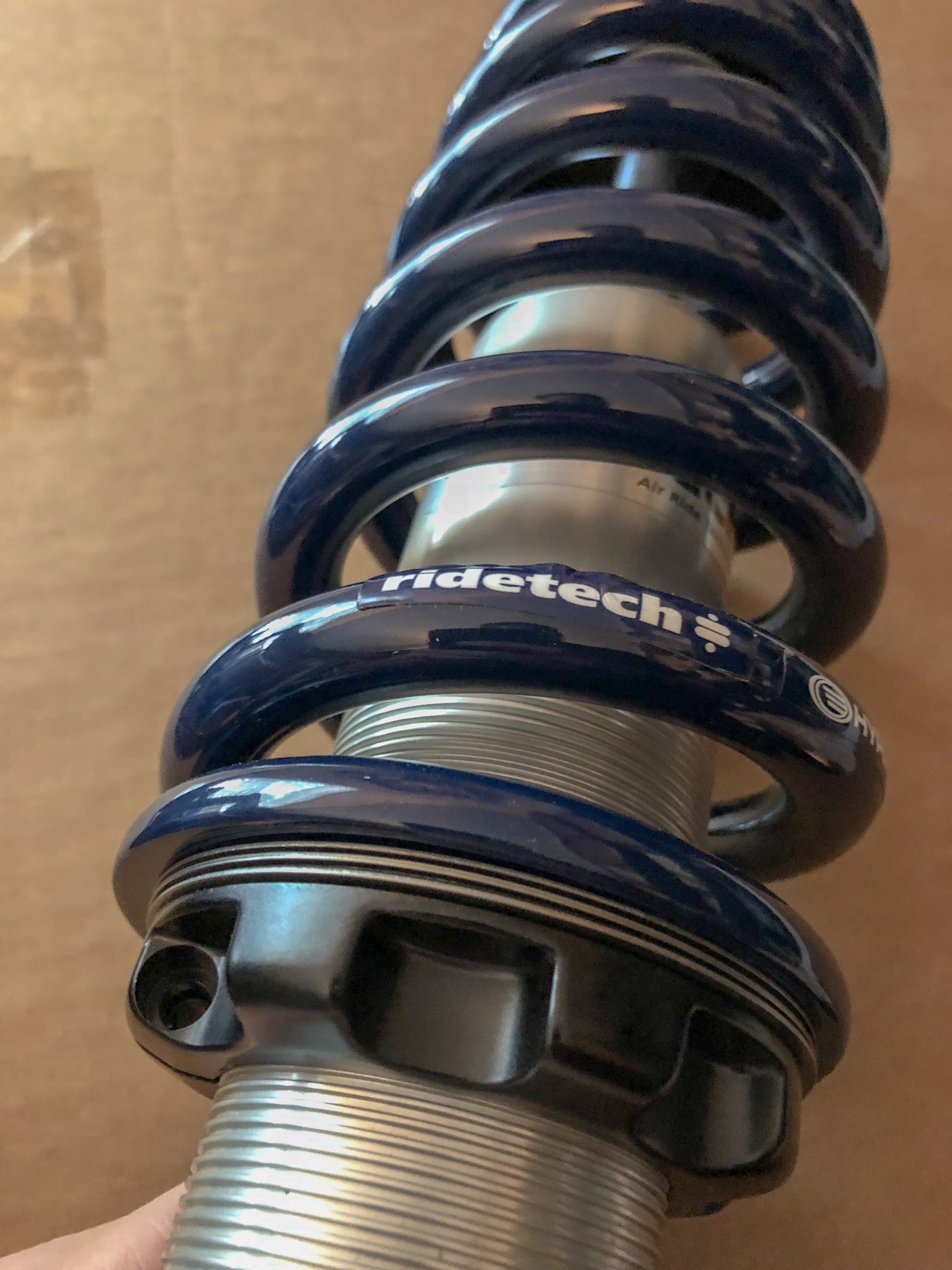
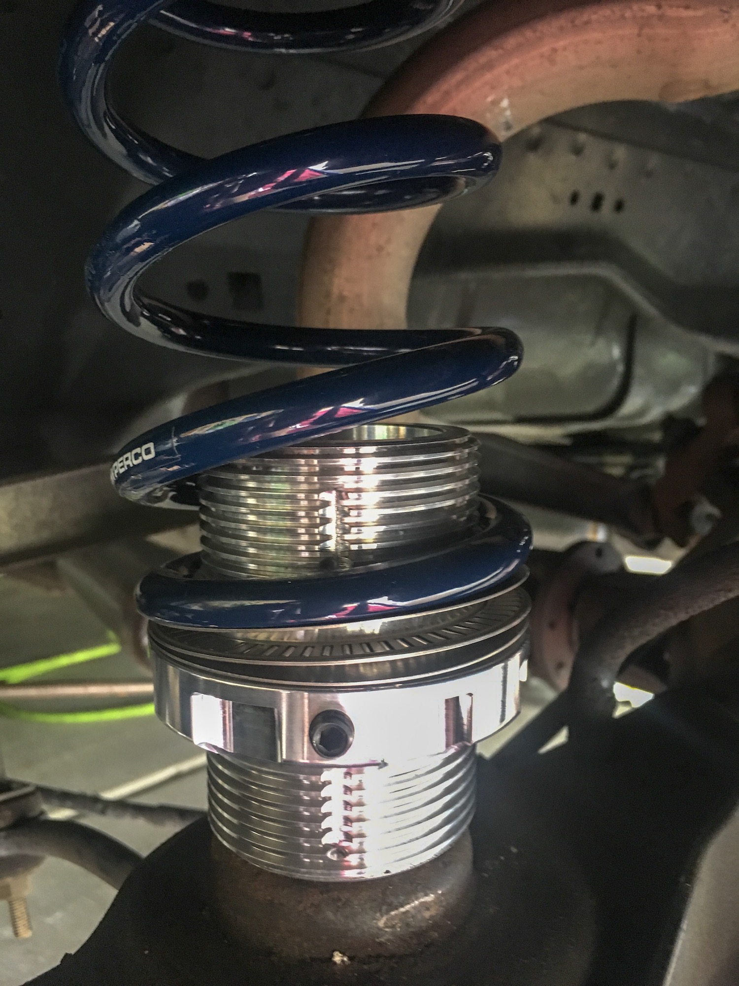
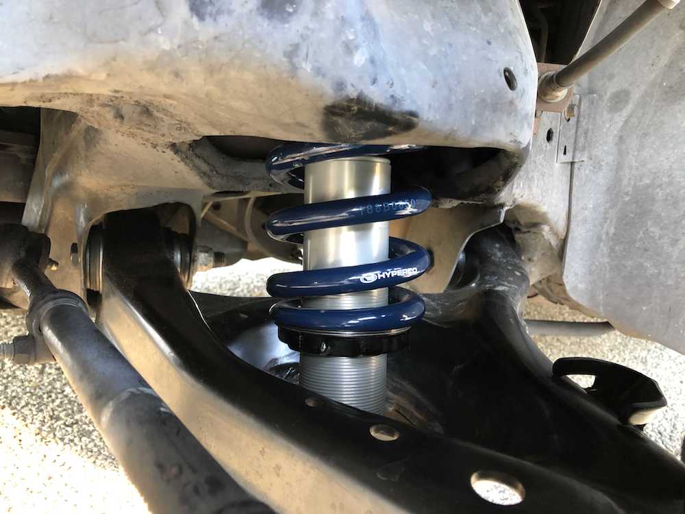
- When assembling the coil over, screw the lower spring perch tight up to the spring (0 preload). You will adjust the lower spring perch once the coil overs are installed on the car to adjust the ride height of the vehicle. Below are some assembled shots of the complete assembly ready for installation
- Now that the coil over assemblies are all put together, lift the front of the car and put the car on jack stands. It needs to be decently high as you need the lower control arm to be able to droop enough to remove the factory coil springs. Remove the front wheels and we suggest removing the front brake rotors and calipers for better access. Remove the factory shocks by removing the upper retaining nut in the engine compartment and then the bottom two bolts at the lower control arm. They should drop right out.
- The next part is the fun part. I put a chain through the spring and run it through the lower control arm to prevent it from shooting out and run a bolt and nut through the chain links to connect them. Put a jack under the control arm at the lower ball joint. I disconnected the upper ball joint to spindle and slowly lowered the control arm. BE CAREFUL TO AVOID THE SPRING SHOOTING OUT AND HURTING YOU! You may need a pry bar or long screw driver to get the spring to unseat from the lower control arm.
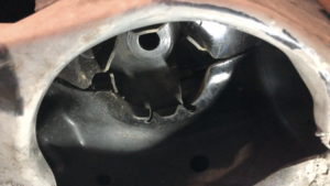
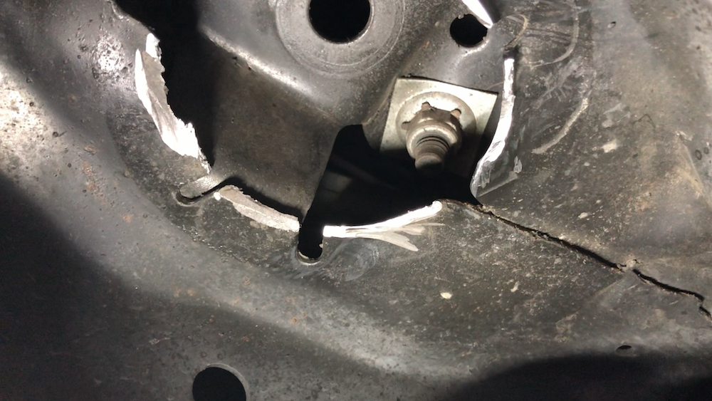
- Once the springs are out of the way you can get to work on the upper frame modifications. You need to remove the stock upper spring locating ears on the frame as the coil over upper spring perch will run right into them and won’t allow the coil over to mount to the frame. Use an angle grinder, cut off wheel, whatever you prefer to remove the ears from the frame. We used some Rust-oleum to cover the bare cut metal when we were done. Below is a picture of before and after:

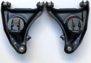
- Because of the design of the factory lower control arm we had to create a lower mounting bracket to help reinforce things and make the system safer. You had two choices when ordering the kit. You could either get a complete lower control arm with the brackets already welded on or the brackets themselves and you’ll have to modify your existing lower control arms and weld them yourself. If you want to see a video on how to modify your control arms and weld on the brackets check the following link: Modifying your stock control arms for ADTR’s 92-02 Coil Over System
- For everyone else there is a left and right lower control arm. Remove the stock lower control arms and install the modified control arms. There is a left and right side so compare to the stock arms to make sure the steering stops and configuration are the same. Don’t torque the control arm bolts to the frame at this time, just make them tight. I decided to not reinstall my stock bump stops. You can install an aftermarket set or modify your bump stops depending on your desired ride height.
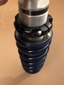
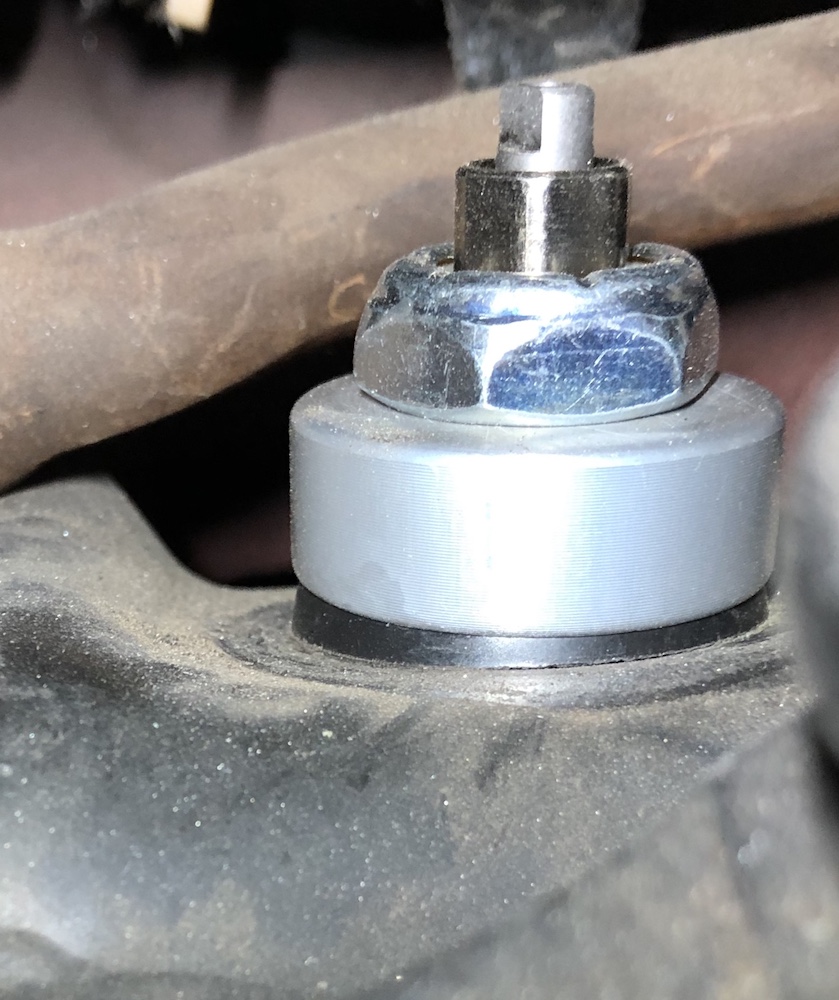
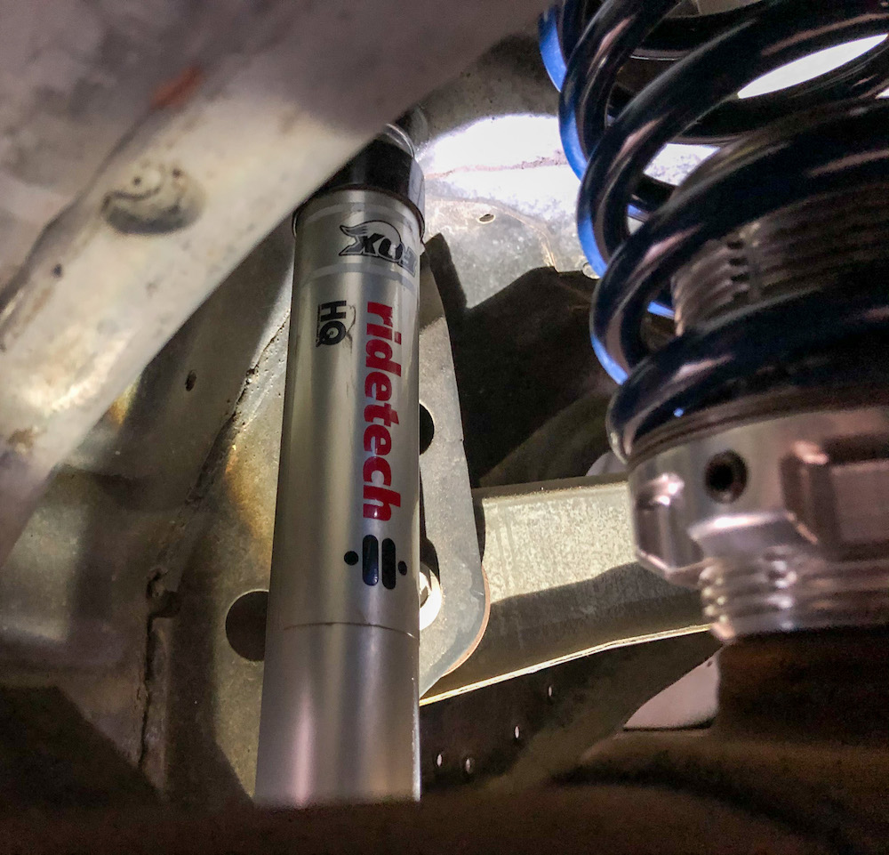
- Install the coil over assembly using the supplied hardware. You’ll have to remove the adjustment knob on the top to loosen the lock nut. The upper shock mount bushings sandwich the frame. Once installed it should look like the first picture below. I waited to tighten the nut until the vehicle’s weight was on the tire. After the upper nut is on and the coil over is dangling from the frame, grab the stepped spacers as seen in the picture below and insert them into the lower coil over bearing. Lift the lower control arm, align the holes and insert the supplied 1/2″ bolt with hardware and tighten. Final assembly of the lower mount is shown in the second picture below:


- Reassemble the spindle and torque the respective parts. Upper ball joint retaining bolt: 66 lb-ft / Lower ball joint nut: 80 lb-ft. Reassemble the brakes and put the wheels back on the car.
- Carefully lower the car to the ground to see where ride height is. Assuming no rubbing or hitting, jounce the suspension and roll the car forward and backward to alleviate suspension bind. Because it’s a linear rate spring you can adjust the ride height of the vehicle by adjusting up the lower spring perch. Lift the corner you want to adjust and using the spanner wrench adjust up to get to your desired ride height. On these shocks up to 1.5″ of preload is acceptable. If you crank that lower seat up too high you can cause coil bind which will cause ride quality to suffer. Do your final ride height adjustments on the car once you’ve got the rear installed. When you are finished adjusting the ride height, don’t forget to tighten the set screw to lock the bottom spring
- We recommend having ramps to allow you to get under the car to torque everything once it’s at ride height. If you don’t have ramps then put jack stands under the control arms and allow the weight of the vehicle to rest on the jacks. You will damage the control arm bushings if you do not follow this step and cause binding in the suspension. Torque the control arm to frame bolts to 110 lb-ft and the upper coil over mount nut to 30 lb-ft
- Now that the upper coil over mount nut is tight you can reinstall the rebound adjuster knob and adjust. Turning the knob to the left makes it softer and to the right makes it firmer. We suggest adjusting to full firm and then backing off 7 clicks to start. You can adjust from there to your personal preference.


Rear:
*If you have air suspension flip off the switch in the trunk located on the driver’s side*
1.) Lift the rear of the car and put jack stands on the frame in front of the rear axle. Leave the jack under the center of the differential to give support. Remove the wheels and tires so you have ample room to access everything.
2.) Remove the stock shocks making sure to keep the jack under the center of the differential housing.
*If you have rear air suspension (and are keeping it) skip to step 6* If you are removing air suspension and upgrading to our full coil over system follow the factory removal of your stock air bags.
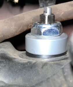
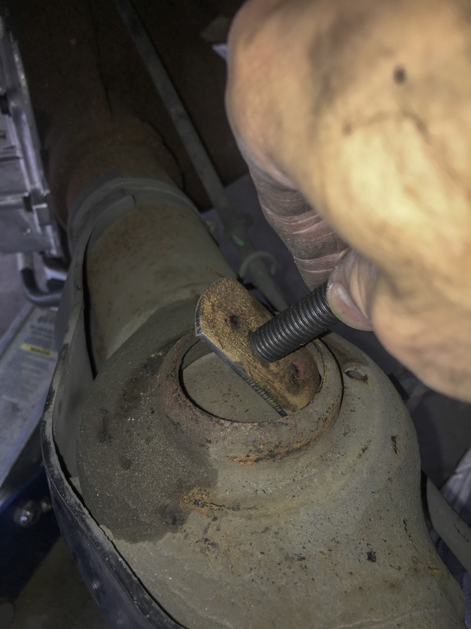
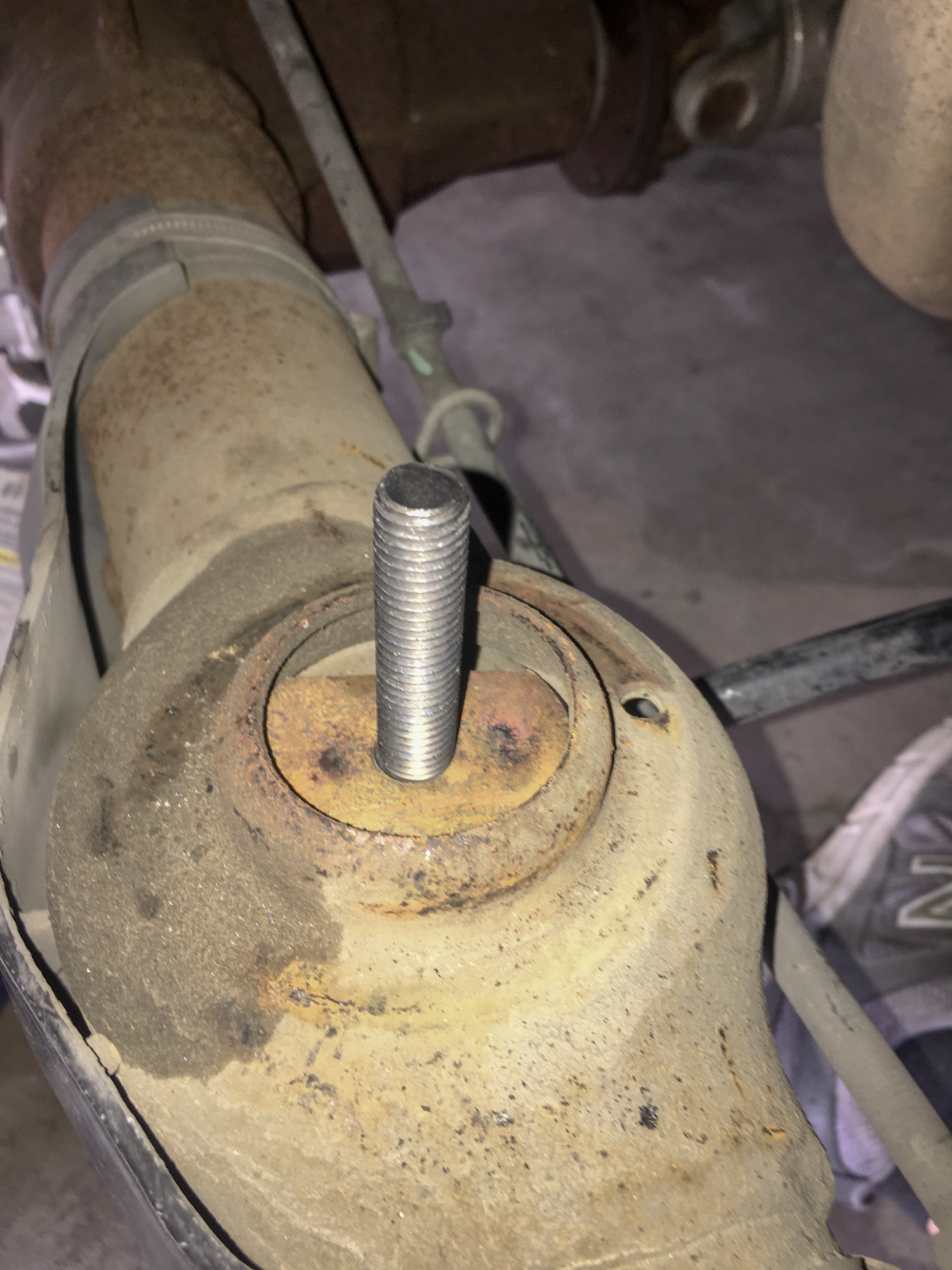
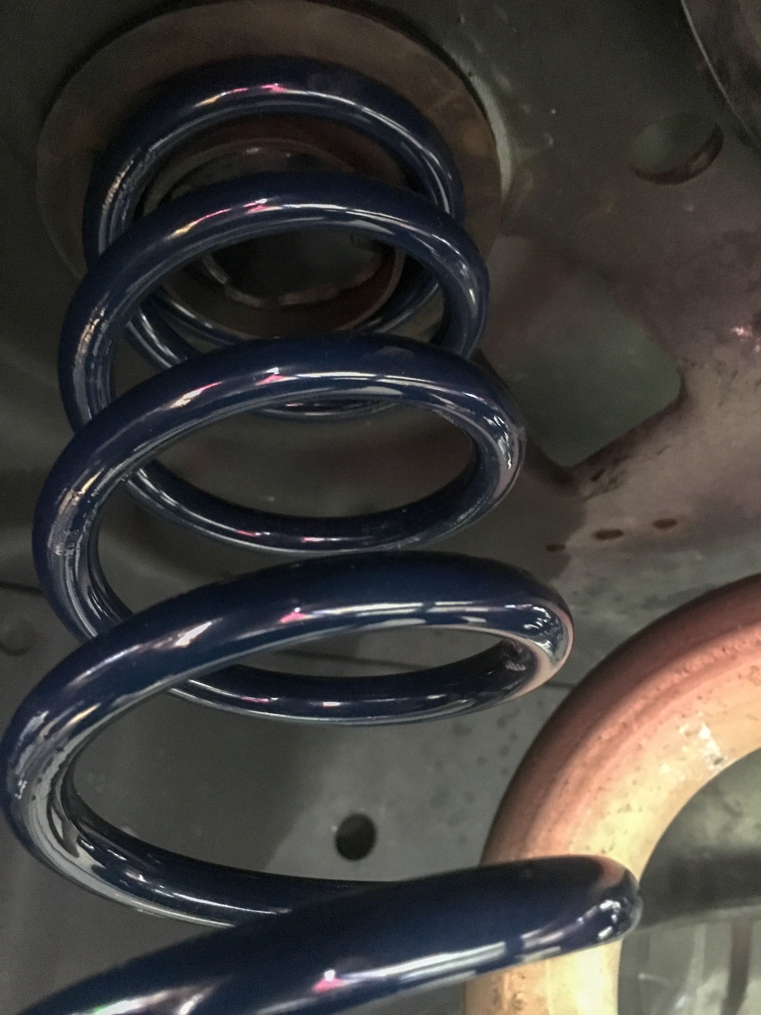
3.) Slowly (AND CAREFULLY) lower the rear differential until the springs pop out of their seats. On the top of the differential housing you’ll find the factory lower spring perch. Take the tabbed bolt and install into the hole in the factory lower spring perch on the differential housing. It should fit pretty tight. Then take the adjustable spring perch threaded body and set it down over the bolt. Tighten the nut.
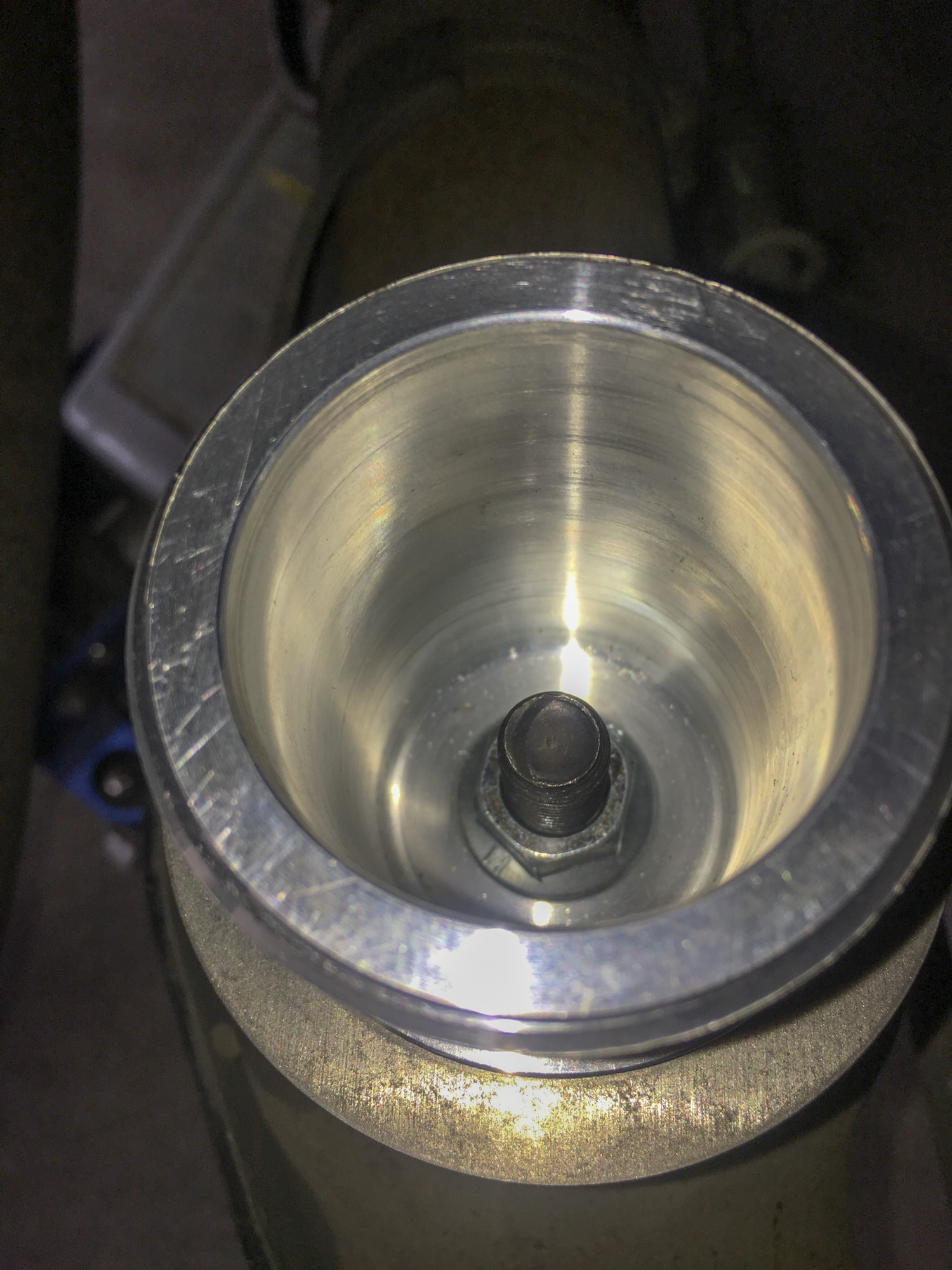
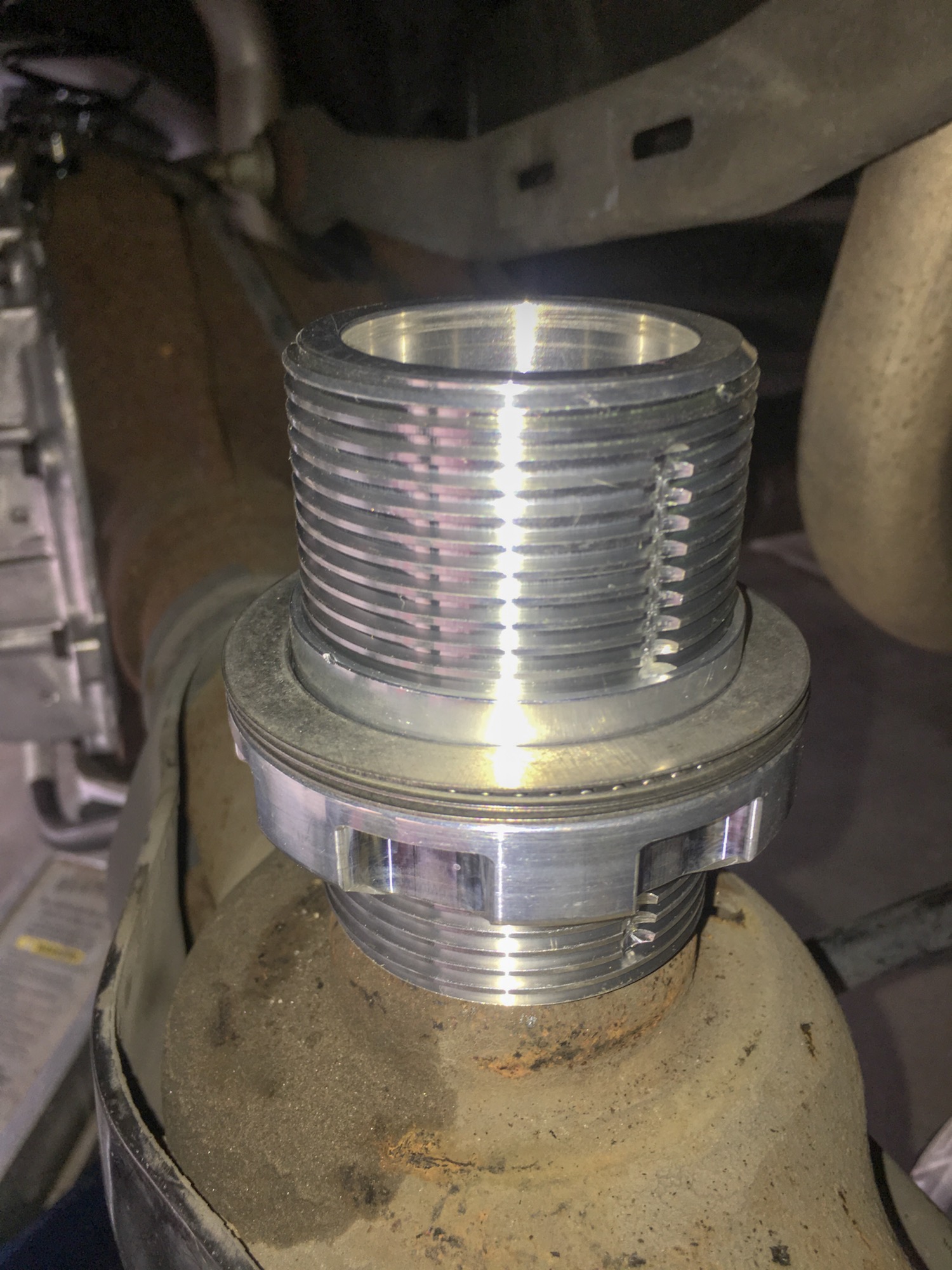
4.) Take the thrust bearings and set onto the lower spring perch. The orientation is the same as the front: washer / thrust bearing / washer. Below is a picture of the completed perch with thrust bearings installed. Apply some general purpose grease to help them stay lubricated. We normally suggest a starting point of about half way up the threaded body.
5.) Take the supplied spring (Our standard kit is a 10″ long 200# spring) and install over the adjustable perch. Use the stock Ford upper spring isolator and place it on the top of the spring. Slowly lift the rear differential housing using the jack under the center of the pumpkin until the springs make contact with the upper spring orienting tabs on the frame.
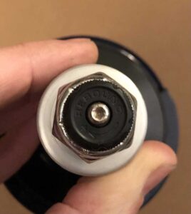
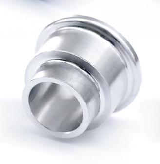
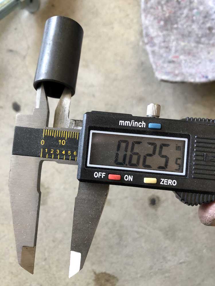
6.) Time to install the rear shocks. Insert the Ridetech supplied .625″ sleeve which should be a good fit on the QA1 lower shock mount studs. The second picture below shows how the stud should be installed into the bottom of the shock. We had to drill out the holes slightly in the rear axle housing tabs as the QA1 stud is a little larger than stock. To make shock adjustment easier, make sure the adjustment knob is pointed towards the center of the car. Take the shocks and install the top into the frame and allow it to hang there. (You don’t need to tighten the nut just yet) Lift the rear end differential housing until the lower shock studs can be inserted into the mounting tabs on the rear differential housing. Tighten the nuts on the bottom and then go back and tighten the top nuts. As far as rebound settings go, like the front we suggest adjusting the shock to full firm and then backing off 7 clicks to start. You can adjust from there to your personal preference.

TORQUE SPECS: – Upper stud to frame – 30 lb/ft / Lower bolt to axle – 66 lb/ft
7.) Now time to adjust the rear ride height
*If you have rear air suspension, don’t forget to flip back on the rear air suspension switch in the trunk.*
For spring equipped cars: Adjust the rear spring perch to get ideal ride height. It may be necessary to lift the car or remove the wheels and tires to access the adjustment points. Turn the perch clockwise to raise the vehicle and counter clockwise to lower the vehicle. Once completed line up the set screw to the closest machined slot on the threaded body and tighten. We recommend measuring from the bottom of the frame to the ground to accurately check ride height. With the rear set, check the front height and make any necessary adjustments. After making sure front and rear is all tight, go take a drive and re-check height. Adjust as necessary.
For air suspension cars: Adjust the rear ride height by adjusting the bracket on the watts link to get your desired height. For more information check out our other Knowledge Base thread here: How to Adjust Your Rear Ride Height
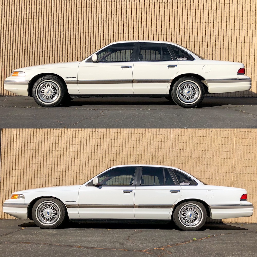
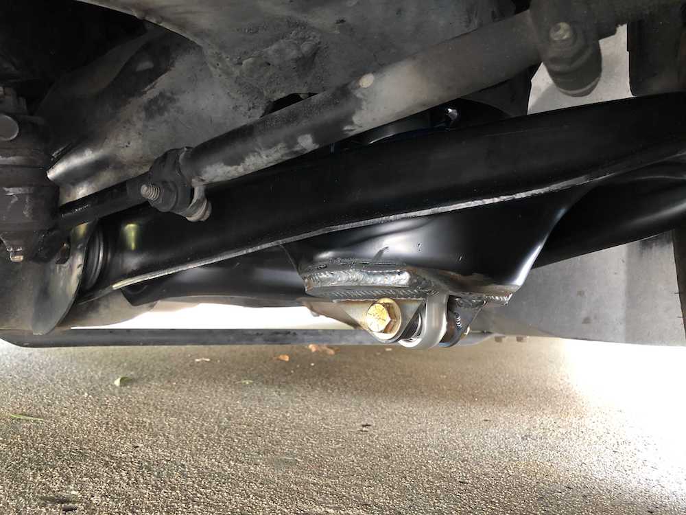
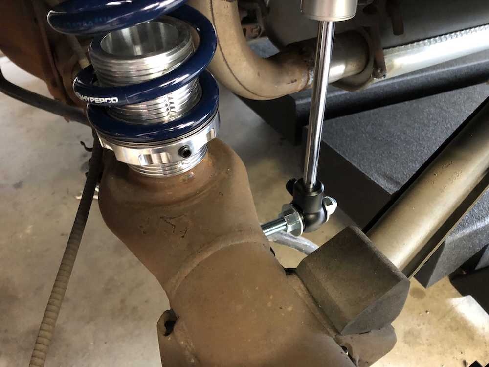
Below are some pictures of what the final product should look like:
Before you drive the car, make sure that your fender lips are rolled and you have ample clearance between the body and the tires to avoid doing any damage. After driving the car around for day or two I like to put the car back on the rack and do a visual check to make sure everything is tight and in good shape.
DON’T FORGET TO REGISTER YOUR SHOCKS WITH RIDETECH TO GET YOUR 1,000,001 MILE WARRANTY WITHIN 30 DAYS!
For more information on the warranty check out the following link: Ridetech Shock Warranty