— Article re-posted from drock96marquis’ tech page on Crownvic.net —
For Non-Marauder and pre 05 panther owners, the ability to monitor engine RPMs is lacking with the factory instrumentation.
The following documents installation methods of a tachometer in ‘92-‘95, ‘96-‘97, ‘98-‘02 and 2003-2005 panthers (specifically, the CV/GM)
(Note; an 03-04 MM or 05+ panther cluster w/ tachometer would require more extensive modification – this write-up is for installing an aftermarket tachometer.)
- Materials:
- -Electrical tape
- -Heatshrink tubing – 10-20 awg sizes
- -12-18 awg wire, preferably in different colors
- -3/8″ wire loom
- -Assorted female and male spade terminals
- -RTV silicone
- -Assorted bullet connectors
- -Autometer 9117 Tach Adapter (98+)
- -Tachometer (see below)
Tachometer requirements:
There are many choices for your tach, and various sizes to choose from.
The Tach you purchase must be a non-diesel, electronic 8 cylinder compatible tachometer.
Note, most of the gauge pod offerings use a 2 1/16″ gauge opening. Autometer makes a very nice tachometer in this size that compliments the analog cluster nicely and ADTR offers it here: Autometer Z series Tachometer
There are also digital tachs which would match a digi-dash cluster quite nice.
Search some on Crownvic.net’s Body/Interior forum for more pics and ideas.
Electrical hook-up:
Tach Signal:
92-95:
- 1992-1995 panthers do not need a tach adapter for a tachometer install.
- You should source the tach signal from the tan/yellow stripe wire at terminal #2 of the EDIS module.
- The PCM is sensitive to signal noise on this wire, so make a nice clean tap and route with care.
Pinout:
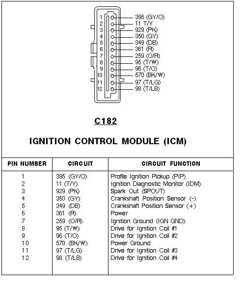
I would solder your tach signal wire to the EDIS terminal #2 wire, using heatshrink tubing over the joint.
From here the tach signal wire goes right to the tach, set it to 8 cylinders.
96-97:
- 96-97 ALSO do NOT need a tach adapter to wire in a tach adapter.
- 96-97 owners can drill out the blank fill on pin 48 on the PCM harness/connector
- As it turns out, this pin is actually the output for the tachometer for similar year 4.6 Mustangs as well. Our panthers (-97) just had it covered up as a tach was not used (obviously)
96 CV PCM pinout:

(click for fullsize)
96 4.6 Stang pinout:

(click for fullsize)
Here is a picture of that pin, courtesy p71crownvic:
I drilled out the plug, and put a 12 gauge wire in the hole, long enough to reach the face of the connector. With the 12awg wire being so dense, there is no way the pin could not make great contact. I then adhered the wire to the connector, reattached the dust boot, put loom over my signal wire to make it look totally factory, and then re-connected the PCM harness/connector.
12 awg was a bit large, 18 awg is better as I did have to trim away a few strands to make it fit.
This tach source also requires an 8 cylinder tach setting
1998-2005
- 98+ cars require a tach adapter to generate a tach signal
- I recommend the Autometer 9117 tach adapter, which is what I will demonstrate in the wiring diagrams below.
- You will need to wire the tach adapter inline of the factory COP power feed (Red wire with light green stripe, all years ’98+)
- This can be done at either the EEC diode, or at the main engine harness connector.
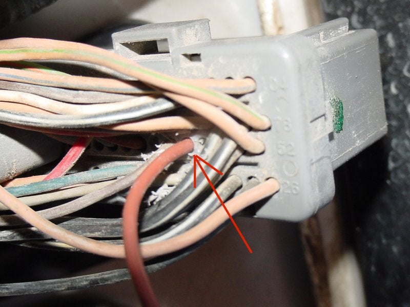
- On 1995-2002 vehicles, the EEC diode is located in the LH fender well relay block, seen here:

OR, I highly recommend you instead use the Red/Light Green striped wire at the main engine harness connector below the brake master cylinder. This wire is on Pin 34, which is right in one of the square connector’s corners. You’ll see it right away.
This location is easier to access and less likely to confuse with another wire (it’s the only R/LG wire on the connector), however the splice will be clearly visible, if you are concerned.
Personally, after helping A LOT of people who mistakenly cut the wrong wire with the EEC diode tap method, I now highly recommend you wire the tach adapter to this location instead and save yourself any headache.
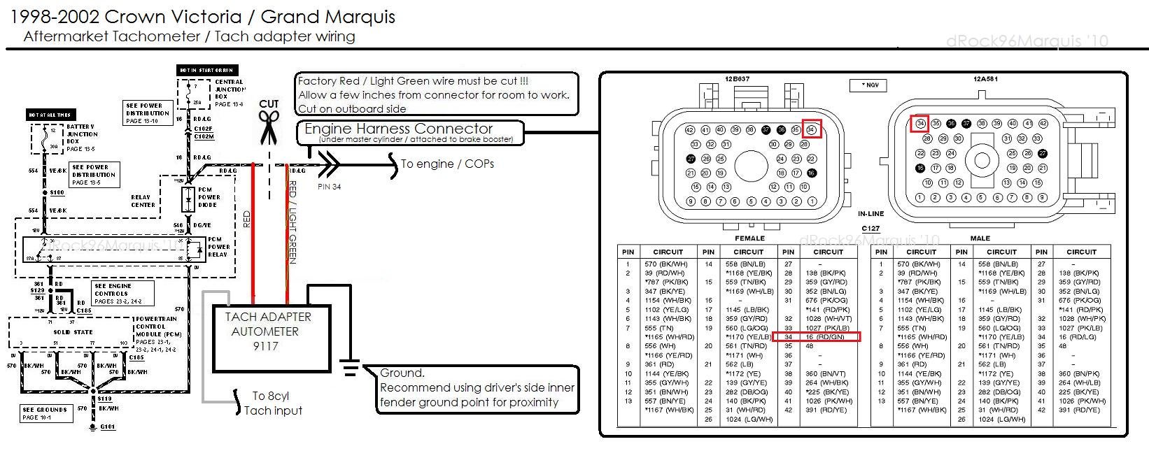
Here is a schematic of how the Autometer 9117 needs to be wired in the ignition system:
’98-’02;
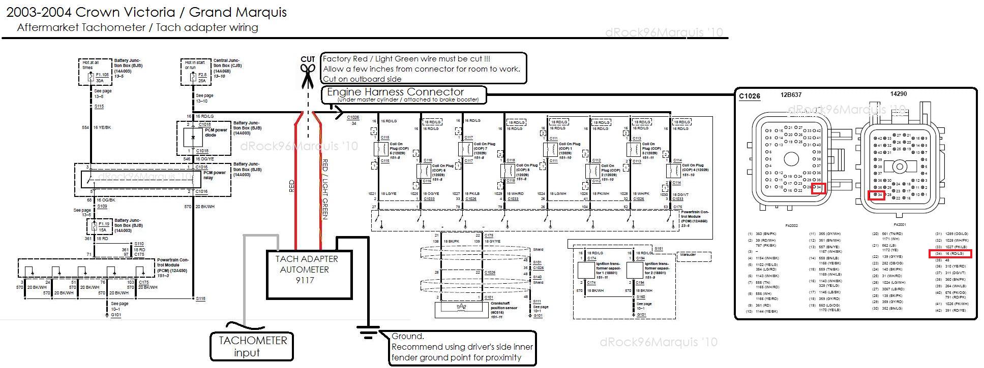
’03-’04;
Wiring the tach adapter is simple! Locate the engine harness connector located directly below your brake master cylinder. It is a large square connector;

(click for fullsize) (Image shown for ’03-’05, ’98-’02 similar)
The COP power feed is the RED/LIGHT GREEN stripe wire is on pin 34 of the main engine harness connector (c1026 03+) under the brake booster
Here is the pinout for reference purposes (’03-’04):
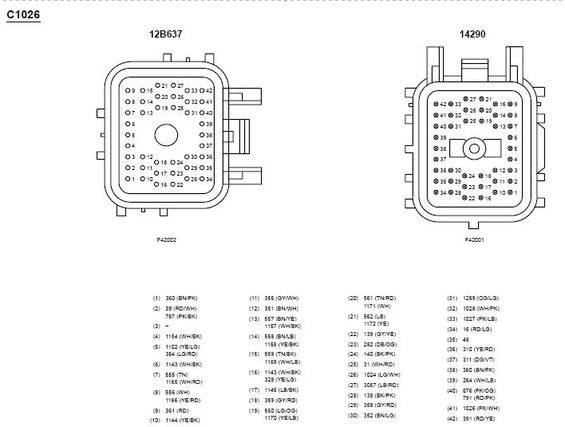
(click for fullsize)
The tach adapter is going to be wired INLINE of this Red/Light Green wire. Cut the wire as far back from the connector as possible so you have room to work with, unravel the harness tape/loom if needed.
Following the diagram above, wire the Tach Adapter’s RED wire to the UPSTREAM side of the cut Red/Light Green factory wire. Upstream would be the outboard side, or closer to driver’s fender
Wire the Tach Adapter’s RED / GREEN wire to the DOWNSTREAM side of the cut Red/Light Green factory wire. The downstream side is the side leading to the engine.
The adapter’s black wire goes to a ground point, and the GRAY wire to your tachometer
The adapter can be mounted to the fender liner, or wherever else desired. Acrylic foam exterior mounting tape will suffice if you do not want to mount it using the screw holes.
Remember! as mentioned above, the Red/Light Green wire MUST BE CUT. The tach adapter is being wired INLINE of the COP power feed, upstream of all coils. It’s not being spliced *into* the circuit, and the tach adapter WILL NOT work if wired as such. The adapter must be upstream of all coils for a correct tach reading.
EEC diode wire tap instructions (’98-’02)
- Slide the relay bank up and unclip the top to expose the wiring. There is a in and out for the PCM diode, you want cut the R/LG wire upstream of the EEC Diode.
- You will see two r/lg wires on the single connector – *typically* you will want the one which is closer the vacuum reservoir when installed. However, note it can be either one of the two wires – so if you have a problem try the other wire (after re-connecting the first)
This picture, courtesy Embassy, shows this:
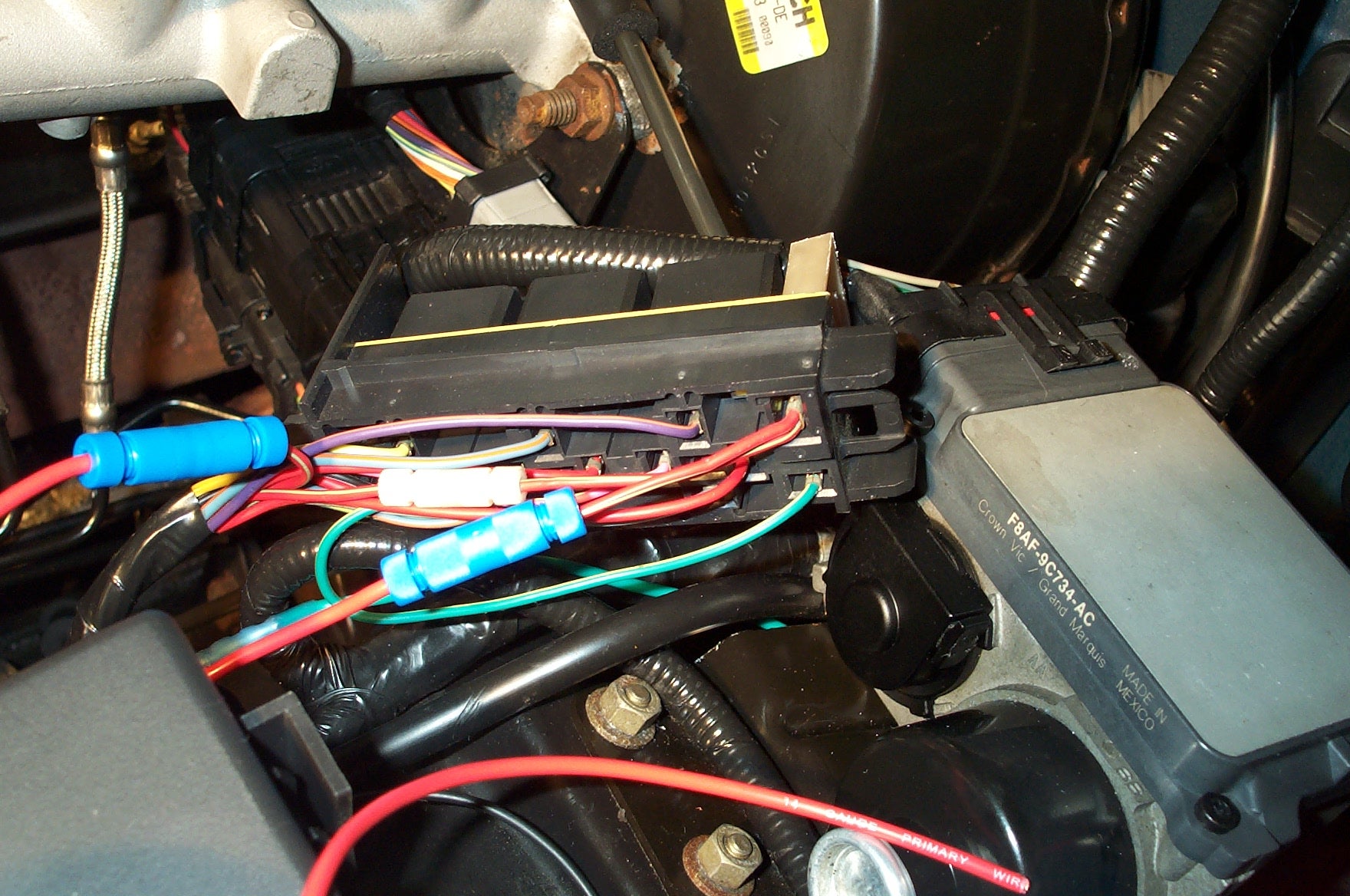
Image Courtesy Embassy
**The wire you see with the white splice connector is the incorrect wire, as Embassy found. The Wire with the two blue connectors is the correct one.
- The tach adapter’s RED wire connects to the lead right off the EEC diode. The Tach adapters RED/GREEN wire needs to be routed to the other end of the wire you just cut. This end is downstream of the tach adapter.
- If tapping at engine harness connector, the RED wire connects to the upstream side of the wire (closer to fender), the R/LG wire connects to the downstream side (To engine/COPS)
- THe Gray wire goes from the tach adapter to the TACH (again, set to 8cyl). The BK wire goes to ground.
- The tach adapter can be mounted in a few spots nearby.
- The -97 power steering reservoir location or on the backside of the relay center work well.
**Note: If you wire the tach adapter as show above and you do not have a tach signal – RECONNECT the Red/Light Green wire you cut and try the other one instead!!!! The position of the COP power wire is not the same for all years or even within the same year, it can be completely random.
EEC diode tap (’03-’05)
- You could still tap the EEC Power diode for a 03-05 w/ autometer adapter install, however the diode was relocated to the battery junction/power distribution box starting the 03 model year.

(click for fullsize)
The wiring color at the Diode output changed as well:

(click for fullsize)
Now the downstream of diode wire is DG/YE, but the upstream/12v input is still RD/LG. On the diagram above, you can see the feed that goes to the COPs, this is where you are cutting.
Given the revised location of the EEC diode, it’s definitely more practical to tap inline of the main engine wiring harness connector at the brake booster – which is actually *much* easier to do.
- If using the Ford Racing Tach Adapter you will be splicing into the CKP sensor wiring instead. THe CKP wire colors are BK/PK for positive and GY/YE for negative (on a 2003 that is). The CKP sensor is located near the harmonic balancer/crank pulley at the bottom of the front timing cover/ FEAD (black sensor body with 2 wire connector)
Illumination:
- Most tachs will have an illumination feature. This is desirable for night-time driving for obvious reasons…
- I suggest sourcing the illumination power feed for your tach adapter from the nearest lit factory switch/component. This will be an orange wire with black stripe for all years 1995 and up.
- For most years, this will be the rear defrost switch (95-00) or the 01+ Power adjustable pedal (if equipped) or Traction Control switches (if equipped) on the LH dash trim piece.
- I like using any of these as it is VERY close to where you will be mounting your tach and of course dims with the rest of the interior illumination using the panel dim switch.
Pinout of the rear defrost switches:
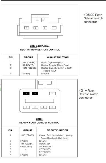
If you choose another switch than a rear defrost, just keep in mind orange with a black stripe is typically always illumination for 92+ panthers and is also true for the 01+ Trac or adjustable pedal switch wiring.
Tach power and ground:
- The tach’s switched 12v power can be sourced from a number of places. I personally prefer the instrument cluster circuit, as a tachometer is instrumentation and this circuit is powered only with ignition.
For 1992-2000 w/ analog dash This is a R/Y wire feeding off fuse #13 on interior fuse panel For 2001-2002 w/ analog dash This is a R/Y wire feeding off fuse #6 on interior fuse panel For 2003-2005 w/ analog dash This is a R/Y wire feeding off fuse #26 on interior fuse panel For 1992-1997 w/ digi-dash DB/LG feeding from fuse #18 on interior fuse panel For 1998-2000 w/ digi-dash BK/WH feeding from fuse #15 on interior fuse panel For 2001-2002 w/ digi-dash BK/WH feeding from fuse #14 on interior fuse panel For 2003-2004 w/ digi-dash BK/WH feeding from fuse #14 on interior fuse panel - This circuit is fused as well.
- Ground can be sourced at a sheet metal panel near the tach location (using a ring terminal and sheet metal screw), or at a factory ground point (many available in close proximity)
Routing your wiring:
- All wires you should be run away from moving parts, and kept as short as possible to reduce signal noise. I like to use wire loom whenever possible
- I recommend soldering then heatshrinking (is that even a word? oh well lol) each and every splice/connection.
- I would also recommend that 98+ owners use weatherproof bullet connections on their COP wire tap. This will allow you to easily disable/return to stock.
- Most have found the easiest way to route the tach signal wire is through the shifter cable grommet. This will be the only wire to route into the cabin. Use an awl or similar to poke the hole.
- A minimum 16-18awg wire should be used.
Tach location and mounting:
Depending on what size tachometer you choose, you can install your new tach in a variety of pods.
- All of the gauge pod offerings which we can use require a 2 1/16″ tach.
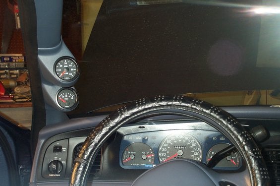
- This is the steering column pod, can be used on all 1995-2004 MM, CV, GM and TC:
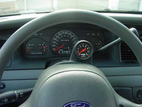
Image courtesy RocketCouch- Check out www.ADTR.net to order either the column shift, or floor shift variety.
- Note; A VDO tachometer may not fit in the shallow Autometer pod. A heat gun or similar may be used to deform/push out the back.
- Both the single and dual a-pillar pods are available at www.ADTR.net There is also an A-pillar gauge pod – also 2 1/16″ and is available in dual or single pod variety.
- this pod is designed for 2003-2004 Marauders, so it is a direct fit for all 2003+ CV/GM
- This pod will also fit 95-02s with some slight modification in the form of trimming and a little molding.
- Here is a picture of my single a-pillar Autometer pod, with VDO vision tachometer:
- I used a heat gun to mold it to my a-pillar, then trimmed it to be a perfect fit and affixed the pod with the included fasteners
- After drilling the holes to fish the wiring, I then sprayed the entire a-pillar with color matching paint.
- Here is Embassy’s dual a-pillar pod, with VDO vision and Volt meter gauges:
(Image courtesy Embassy) - His install came out fantastic. If you click the image you can navigate to his A-pillar install album, with many more pictures.
- Both the single and dual a-pillar pods are available at www.ADTR.net
- There is also the Mercury Marauder gauge pod.
- It fits in place of the ashtray, and provides two 2 1/16″ gauge openings.
Here is a picture of the Mercury Marauder gauge pod installed on my Marquis, neither of the pictured gauges are tachometers, but you get the idea:
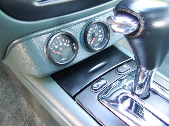
- This pod is a direct fit in all 1995+ panthers, provided you also get the bracket. It comes in black only, so color match is up to you.
- Ford p/n: 3W3Z-5404810-AAB
- And of course, you can do a custom install.
- Here is Dextrovic’s very slick VDO trio:
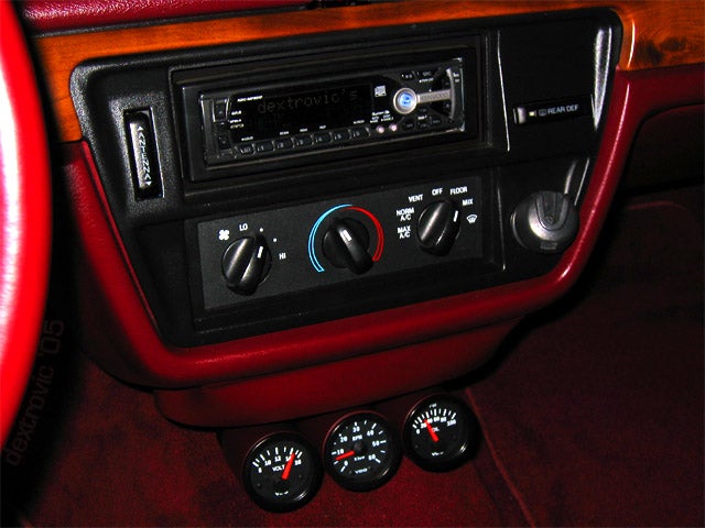
(Image Courtesy Dextrovic) - Affixed to the ashtray door is 3 color-matched VDO 2 1/16″ gauge mounting cups, housing 3 VDO 2 1/16″ Vision series gauges.
- Here is Dextrovic’s very slick VDO trio:
I hope this helps some of you guys get your tach installs done!
For 1995-2005 panther owners who find this all to confusing, a Scan Gauge will be best for you. It plugs right into the OBDII Data-Link-Connector (no batteries) and displays engine RPM among MANY many other readouts. It also computes MPG, trip computer, and is a OBDII trouble code reader/clearer. Check out Scan Gauge’s Webpage