Congratulations on buying our manual swap pedals. These pedals should be fairly straight forward on installation but check out the following tips for any clarification. There may be some variations as this installation shows the process with a TR3650 transmission. As always if you have any questions, please feel free to contact Chris.
Check out the YouTube install video by Pier (yes that Pier) for more in-depth info: Pier’s Installation of ADTR’s V3 Manual Swap Pedals
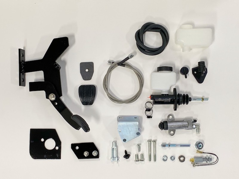
You should have received the following:
- Pedal Assembly Kit (including pedal assy, hardware, weld on brake pad and pedal cover, master cylinder reinforcement plate, master cylinder reservoir bracket, neutral safety switch and master cylinder clevis)
- Wilwood Hydraulic Master Cylinder Kit (including multiple fluid reservoirs, clamps, hoses, reservoir fittings and 90 degree 1/8” NPT to -4 AN fitting)
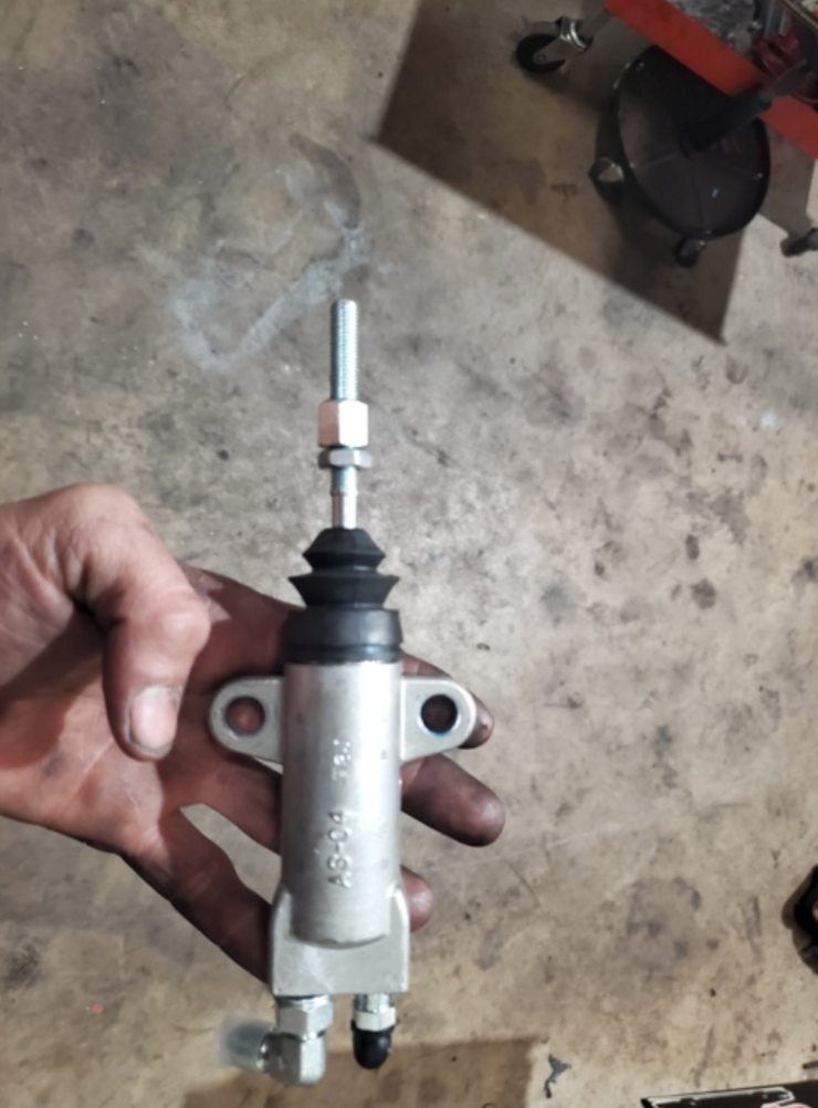
- Hydraulic Slave Cylinder Kit (including slave cylinder, transmission specific bracket, AN line and hardware)
NOTE: It is advised to install the slave cylinder kit and mounting bracket into your manual transmission, PRIOR to installing the manual transmission into your car. (However, if you already have a manual transmission in your car, and are simply changing the pedal assembly, you can install the slave cylinder and mounting bracket while the transmission is in the car)
STEP 1: PEDAL PREPARATION
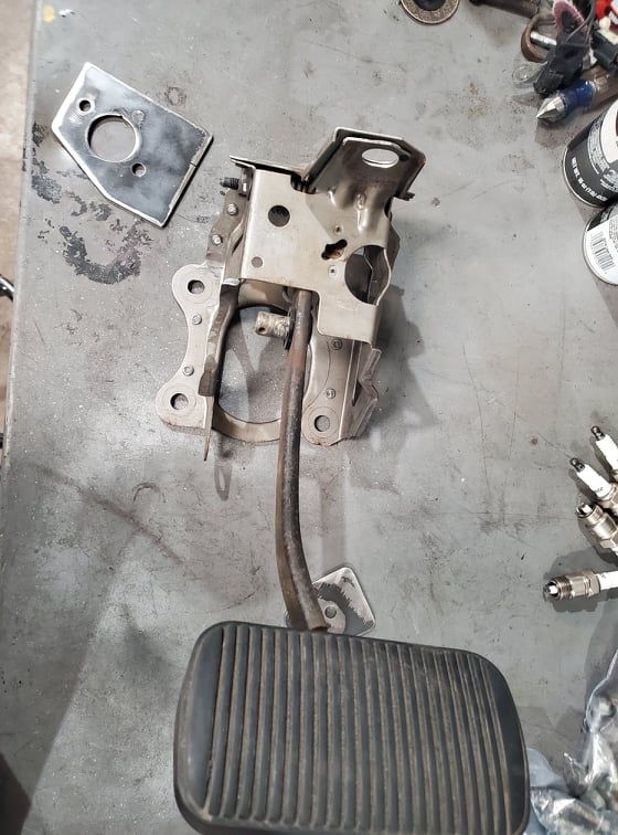
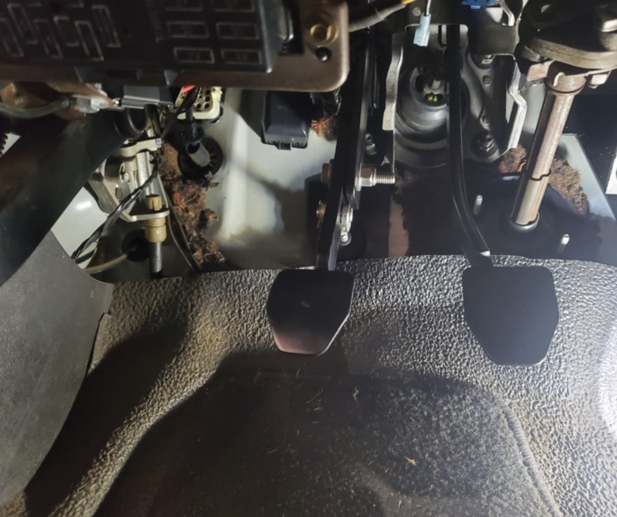
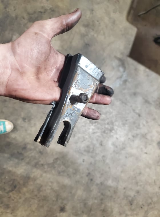
Remove the factory brake pedal assembly from car. If you have adjustable brake pedals from the factory you will need to find a set of non adjustable pedals and swap that assembly into your car. The adjustable pedals uses the second upper mounting location on the dash and that hole is used to mount the manual pedal assembly so unfortunately they have to be swapped. Below is a picture of what the removed assembly looks like:
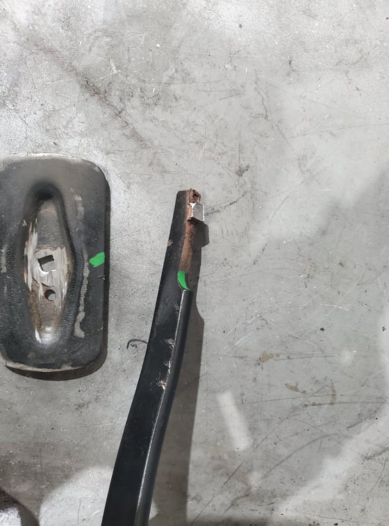
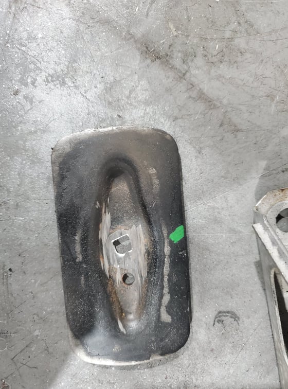
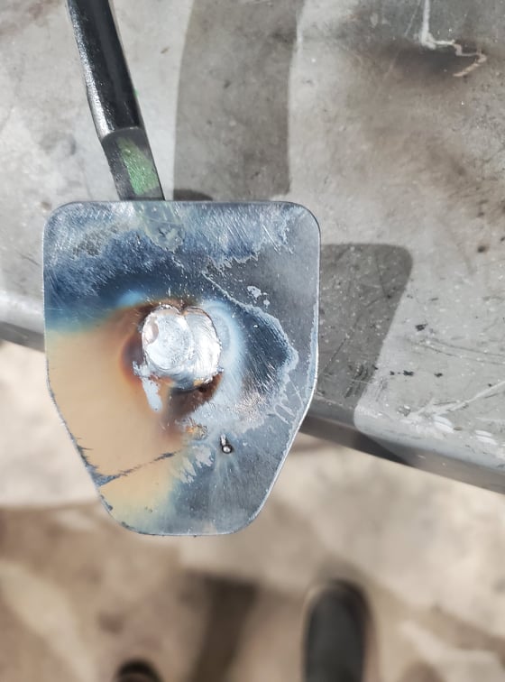
Remove the large rubber pad from the factory pedal assembly. The factory steel pedal pad will need to be removed from the pedal shaft and the smaller supplied pad will need to be welded onto it. You can remove the pedal pad using a grinder or a saw. Be sure to mark the angle of the factory pad that you are removing, so that the manual pad can be installed in the same orientation.
Fit and weld the supplied manual brake pedal pad to the factory pedal shaft. If you are not good at welding we suggest having it done professionally. Having a working brake pedal is pretty important so make sure the welds are done well.
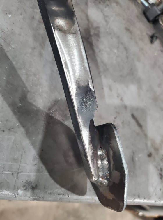
Once it has cooled, install the supplied rubber pedal pad. At this point, the modified factory brake pedal assembly can be reinstalled in the car.
STEP 2: FIREWALL MODIFICATION
After the factory pedal assembly is reinstalled, you will need to modify the firewall. You will have to remove some of the insulation under the brake pedal assembly where the master cylinder plate will be installed.
The Master Cylinder Reinforcement Plate has an angled edge that lines up with the edge on the firewall. There is a cut in the top of the Reinforcement Plate that lines up directly under the brake pedal mounting studs. Position it as shown in the picture below and mark the firewall to drill the holes.
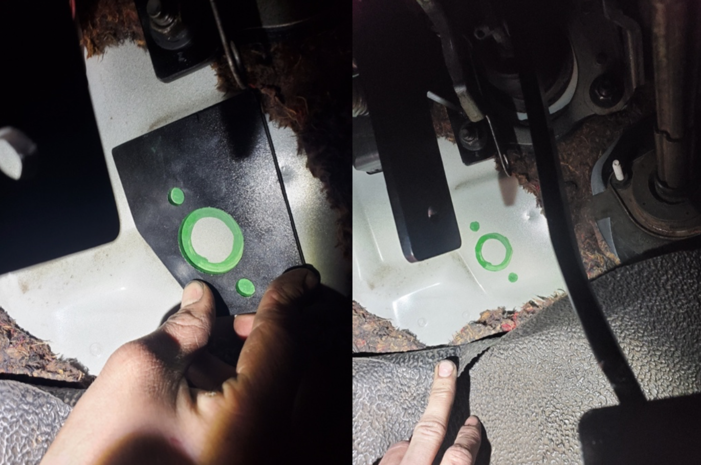
The center hole in the firewall will need to drilled with a 1 ½” diameter hole saw. The two outside holes will be drilled with a 3/8” drill bit.
STEP 3: MASTER CYLINDER INSTALL
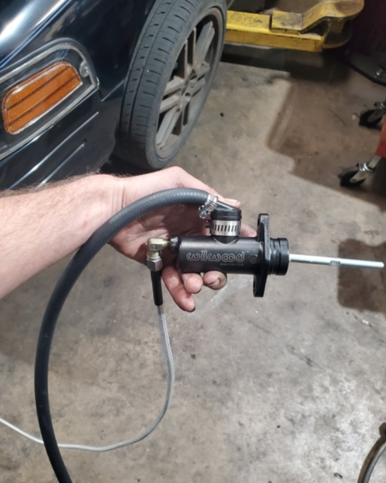
Now is a good time to prepare the master cylinder. Begin by removing the nut and rubber boot from the Wilwood Master Cylinder. Next, install the 90 degree fitting into the end of the master cylinder. Position the fitting as shown in the picture below:
Install the braided hose (supplied with the Slave Cylinder Kit) onto the 90-degree fitting that was installed on the Master Cylinder. Install the push on fitting and hose to the top of the master cylinder with the nipple facing the front of the master cylinder, as shown in the picture below:
The Master Cylinder is now ready to install. Position the master cylinder on the engine bay side of the firewall in line with the holes that were previously drilled. Route the braided hose towards the bottom of the car on the inside edge of the frame rail. Leave the rubber hose accessible from the top side of the engine bay.
From the inside of the car, install the reinforcement plate aligned with the holes drilled in the firewall and the holes drilled in the master cylinder. This may require assistance from another person. Then install the 3/8” x 1” bolts through the plate and the master cylinder and use the nuts on the master cylinder side and tighten.

Once everything is tightened, reinstall the rubber boot and nut back onto the master cylinder.
STEP 4: CLUTCH PEDAL AND MOUNT INSTALL
Remove the two brake pedal assembly mounting nuts on the left side of the assembly. Install the clutch pedal mounting bracket onto the two studs and reinstall and tighten the nuts. Then install the supplied upper mount bolt into the top of the clutch pedal mounting bracket going to the dash support.

Install the supplied clevis onto the master cylinder’s threaded push rod. Position the clevis over the lower hole in the clutch pedal and install the push pin and secure with a cotter pin to hold it to the clutch pedal.
STEP 5: SLAVE CYLINDER INSTALLATION
NOTE: PLEASE REFERENCE THE INCLUDED INSTRUCTIONS WITH THE MODERN DRIVELINE SLAVE CYLINDER BEFORE PROCEEDING.
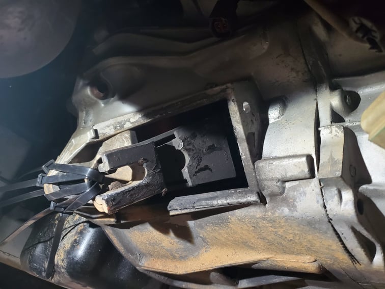
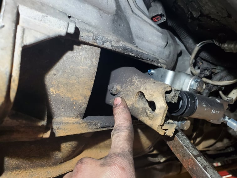
A hole will need to be drilled in the clutch pedal fork box for a mounting bolt. There is an existing threaded hole that will be the guide for the drill. You will need to use a 21/64 drill bit.
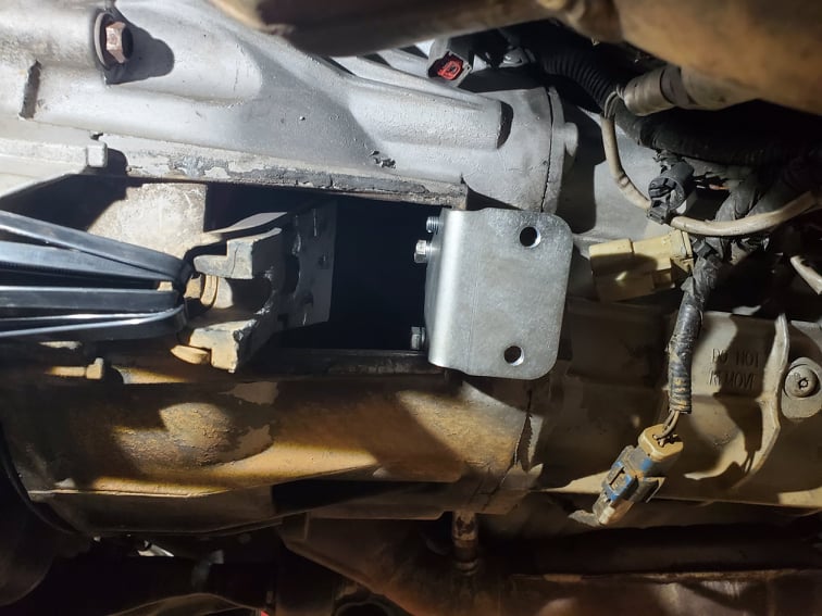
Inside of the bell housing there are two bolts with 13mm heads that will need to be removed. Install the mounting bracket using the supplied hardware through the clutch fork box opening. It will look like this:
If your clutch fork has the factory weight still installed, it will need to be removed. It has one 13mm nut securing it to the clutch fork.
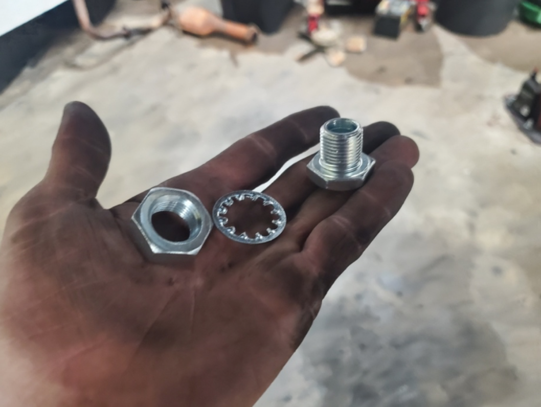
Next, find the supplied socket and nut (shown below) and install onto the clutch fork from the rear with the threaded portion towards the front of the car:
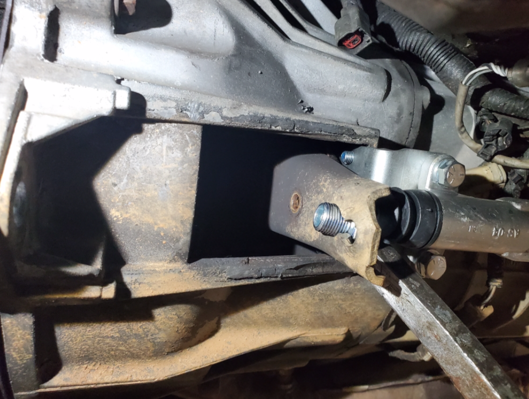
Install the lock washer and then the nut as shown below and tighten both sides using a 15/16” socket and wrench:
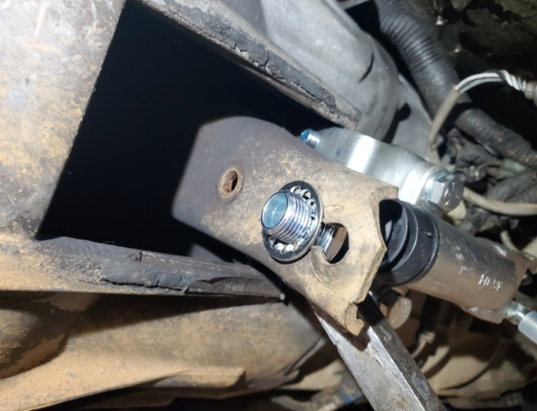
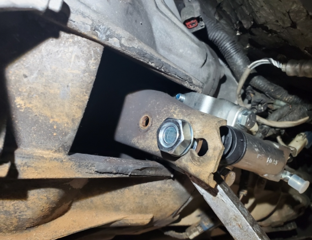
Install the push rod into the slave cylinder and install the slave cylinder onto the mounting bracket on the side of the transmission.

Now that the slave cylinder has been mounted, route the braided hose to the back side of the cylinder. Make sure to leave enough room so that the hose does not come into contact with the exhaust. Attach and tighten to the fitting at the back of the slave cylinder. (NOTE: Depending on what clutch you chose to use and the design of the pressure plate fingers, you may need additional travel out of the slave cylinder to get enough movement out of the pedal for full engagement. You can drill two holes in the bracket to move the slave cylinder closer to the fork)
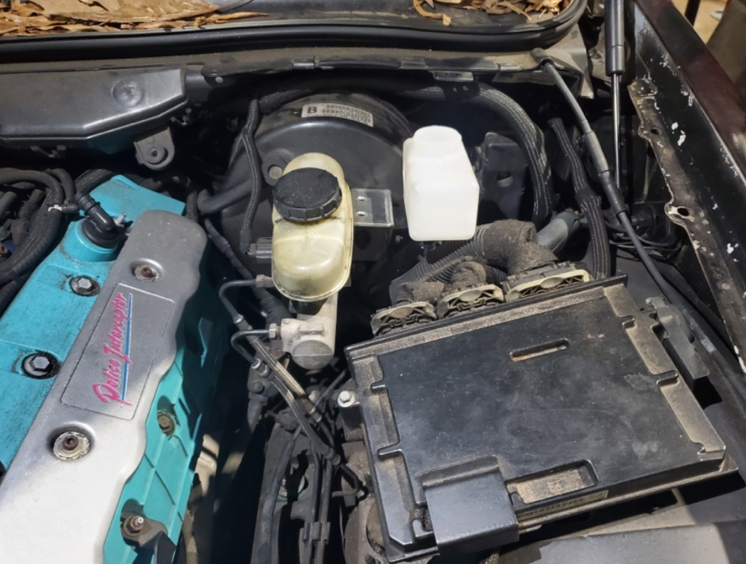
STEP 6: MASTER CYLINDER RESERVOIR INSTALLATION
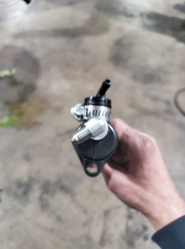
Install the Wilwood-supplied plastic reservoir mount onto the reservoir and then mount the reservoir to the supplied bracket. Using the brake master cylinder mounting nut, mount the clutch reservoir as shown below:
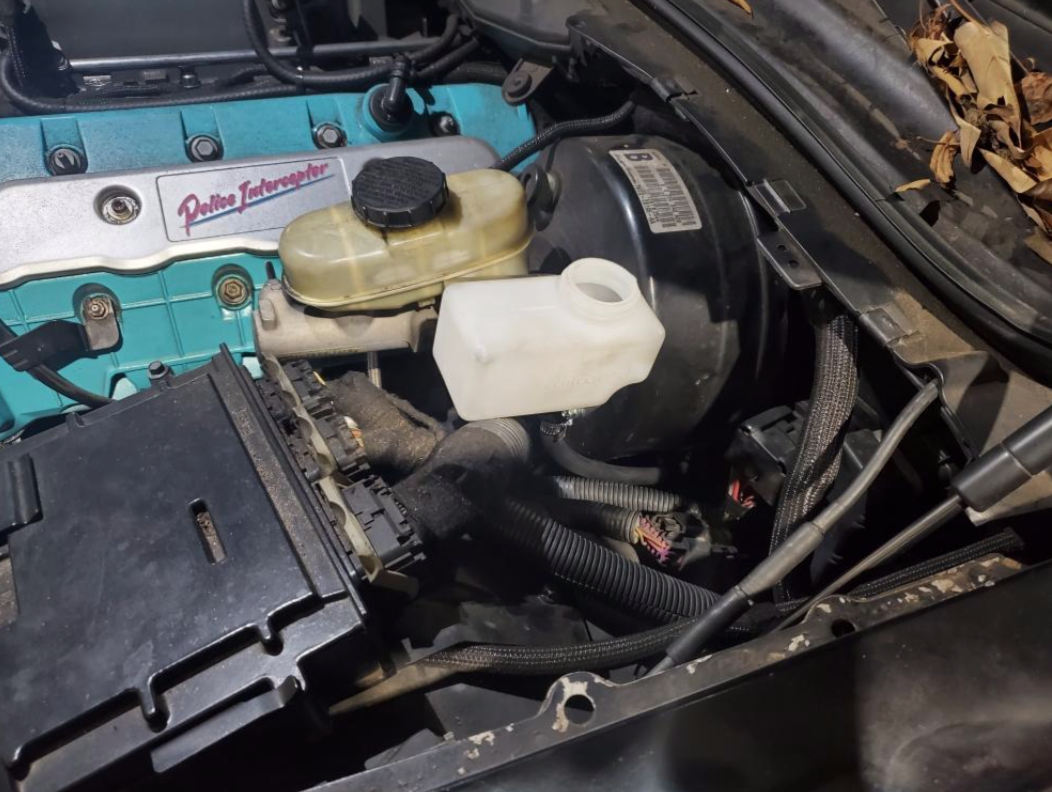
Once the reservoir has been mounted, take the rubber hose coming from the master cylinder and cut to length to fit the bottom of the reservoir. Once it is cut, install the hose onto the reservoir. Reinstall brake master cylinder mounting nut.
STEP 7: FILL AND BLEED THE SYSTEM
To make your life easier, we now include the Modern Driveline bleeder kit with the pedal systems. Check the following link from on how to properly bleed the master cylinder and what fluid they recommend using in the system: How To Bleed Your System
STEP 8: WIRING OF NEUTRAL SAFETY SWITCH