Disassembly:
Drain transmission fluid, remove driveshaft and remove exhaust. Support transmission and remove cross member (It may be difficult to remove as the original is pressed in) Unbolt torque converter, make sure to disconnect the wiring harness after labeling connectors. Drop transmission and remove flex plate.
Clutch / Scattershield:
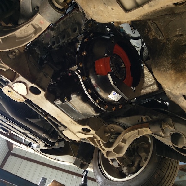
This is fairly straight forward. Install the supplied pilot bearing in the crankshaft. Install the block plate from the scattershield, install the flywheel and follow the directions on the ARP supplied hardware and torque accordingly (70 ft-lbs) Install the clutch and pressure plate and then remaining part of scattershield. Follow the directions supplied with the scattershield and torque all bolts accordingly.

Firewall / Pedals:
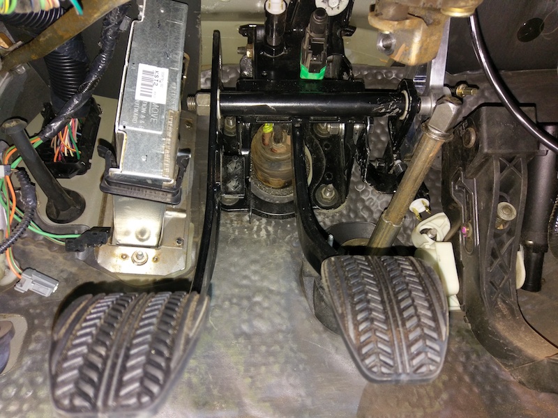
Remove the brake pedal assembly and install the modified brake pedal assembly with clutch pedal. I bolted onto the firewall, marked the cable hole and then removed the pedal assembly to drill the hole/reinforce then re-installed everything. (Make sure the clutch quadrant is installed before installation of booster as it is very tight in there)

Any questions on the pedals you can direct them to me or Pier of Pier’s Pedals in Canada. Here is a great video on YouTube that Pier goes through some of the fitment and fine details of the pedal adjustment and drive by wire throttle pedal relocation: Pier’s Pedals Explained
Transmission Tunnel:
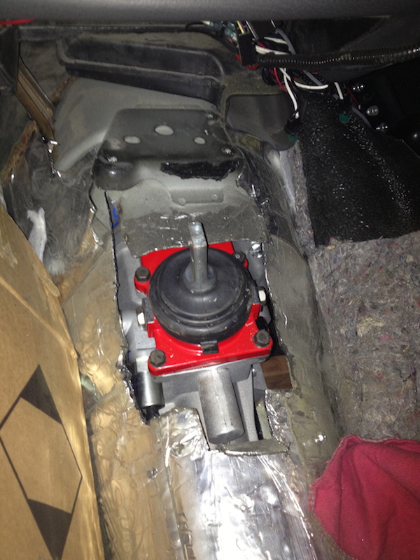
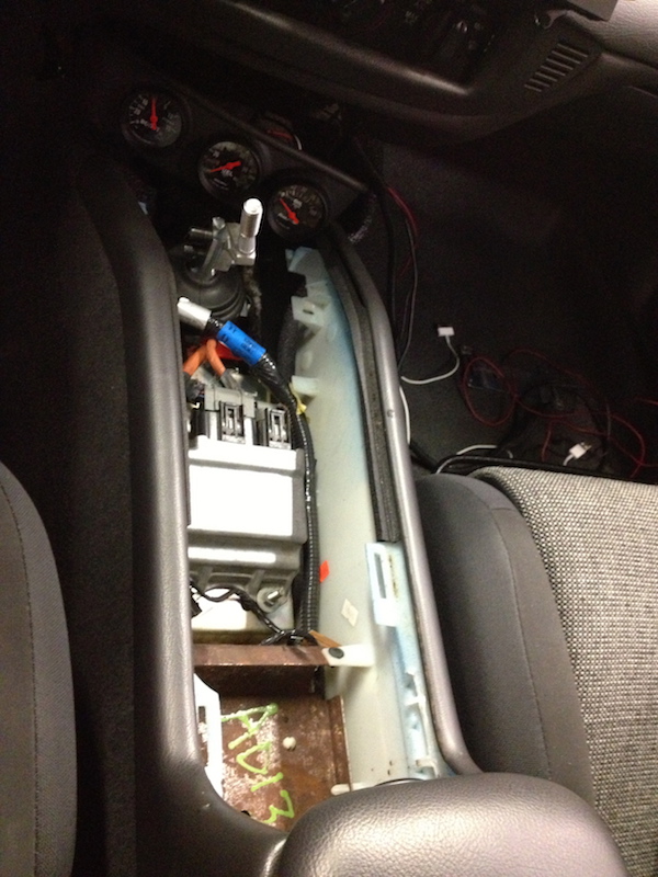
The tricky part is figuring out approximately where to cut. You can always start small and make it larger. I’d still suggest this even given our dimensions as every car is a little different. Take these dimensions as suggestions and go from there. These pics show the overall length of the opening in the floor as well as how far back from the body seam in the front we needed to start the cut. The bracket for the lighting control module had to be removed to allow the floor to be clearanced in the front. I’ll show you later where I mounted it in the Marauder/CV Sport console.
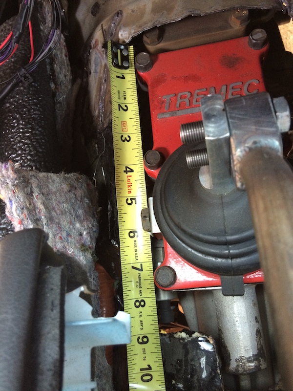

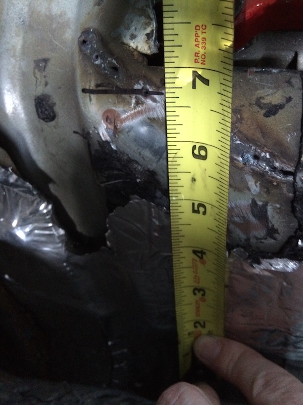
This is the measurement from the edge of the bottom of the driver’s side floor pan (where your feet are) to the front most edge of the hole. We measured 7″ up and started cutting. The second picture is me pointing to a body seam so you can see approximately how far to cut for clearance for the rear of the transmission
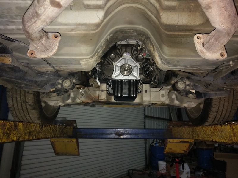
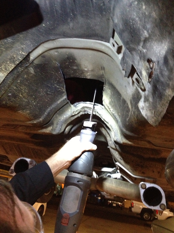
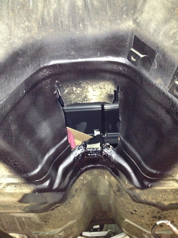
Here’s a shot of the underneath showing approximately where the cuts were made. The front portion was cut and hit up with a hammer to gain additional clearance for the front of the shifter plate. We had to cut an additional 2″ in the back to clear the rear of the transmission. Since it was in a reinforcement in the floor pan we sprayed in expanding foam to seal and then undercoated.
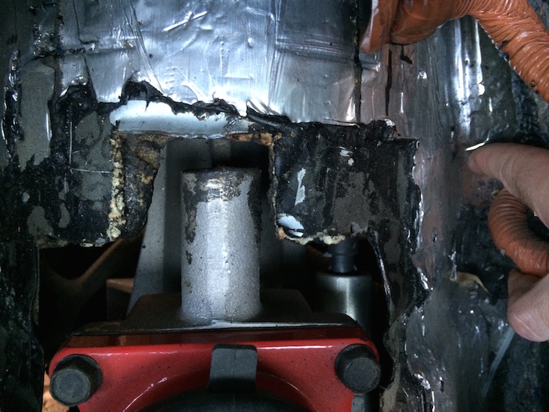
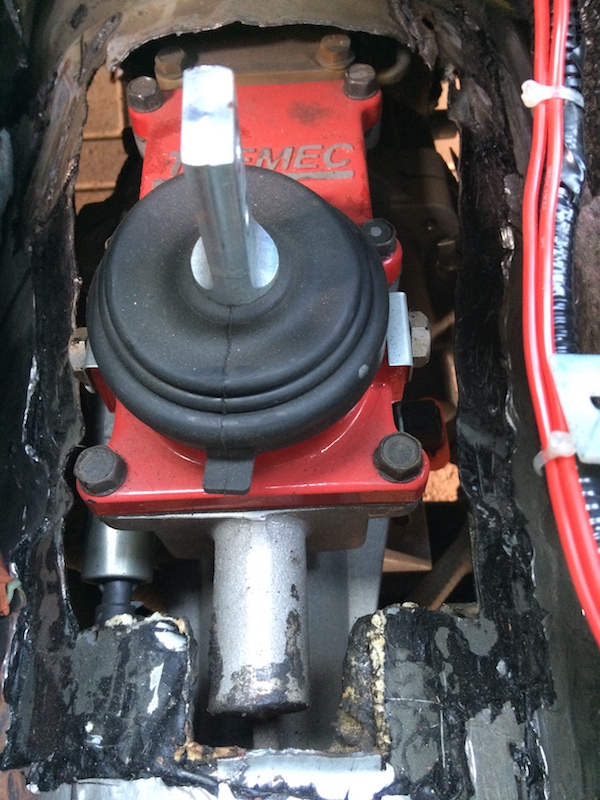
Here’s what it should look like from up top once mounted. In the first picture you can see the bracket for the module that had to be removed to allow the floor to move up for additional clearance.
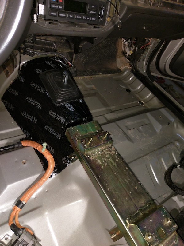
The fabricated transmission tunnel cover we supplied is a 1/4″ longer so you can massage that to the floor for a better seal. I used self tapping screws to secure and you can use more of the self expanding foam or silicone to help seal things up better. I later covered the edges with sound deadening material to help keep noise and smells out of the cabin. You can also see the bracket for the Marauder/Crown Vic sport console and how it will need to be cut and modified to clear the cover. (The shifter handle was there for mock up, yours should not look like that) This picture also does not show the installation of the Mr Gasket boot over the hole in the transmission tunnel cover. Screw down using self tapping screws.

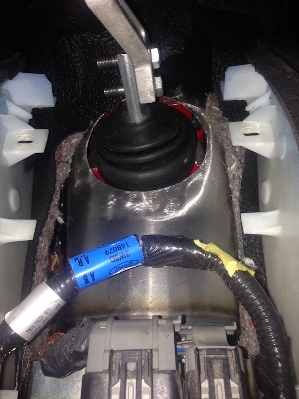
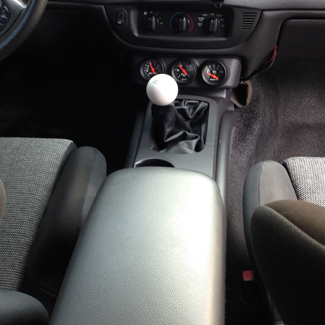
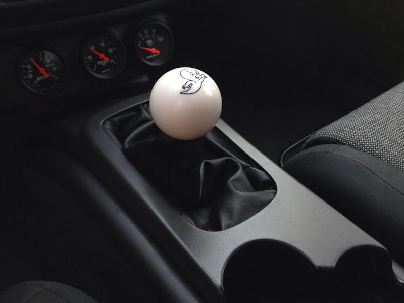
As I referenced earlier the bracket at the base of the dash for some module needs to be cut off for clearance purposes. I mounted the module on the console bracket as seen below. Install the shifter handle and install the leather boot in the Marauder/CV Sport console opening and finalize install in center console. Install shifter handle of choice and you’re good to go!
Transmission Cross member:
Getting the cross member out in the first place can be one of the hardest parts! We used a lot of penetrating lube, big prybars and a lot of weight thrown around to get it off. The factory presses them in. We cheated on reassembly and ground down the surfaces slightly to allow for quicker in and out. It’ll be in and out quite a bit for mock up and welding and painting/coating.
First we cut off the front mounting pad on the cross member. After that we cut the top part of the cross member to fit the supplied bent replacement transmission mounting pad:
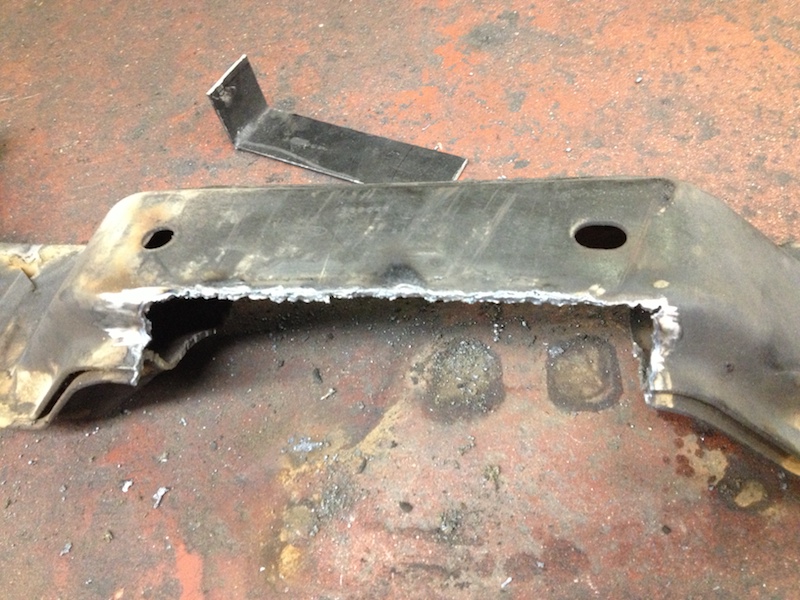
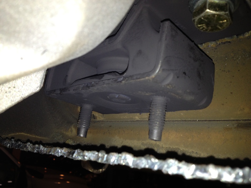
Here you can see what the cross member should look like cut out and installed on the car with the transmission and factory transmission mount installed. The supplied replacement mount pad should fit right around that seam in the transmission cross member and the two ears stick up parallel to the frame rails. Once the new mounting pad is installed just trim the ears of the mounting pad to match the contour of the cross member.
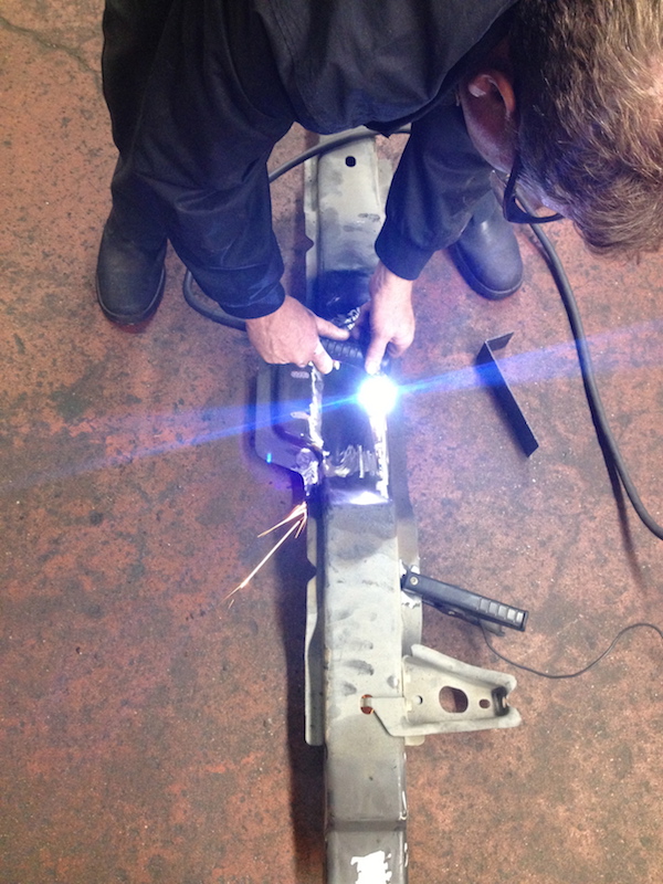
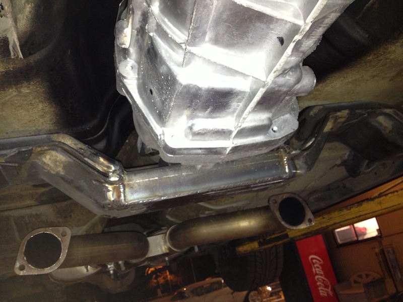
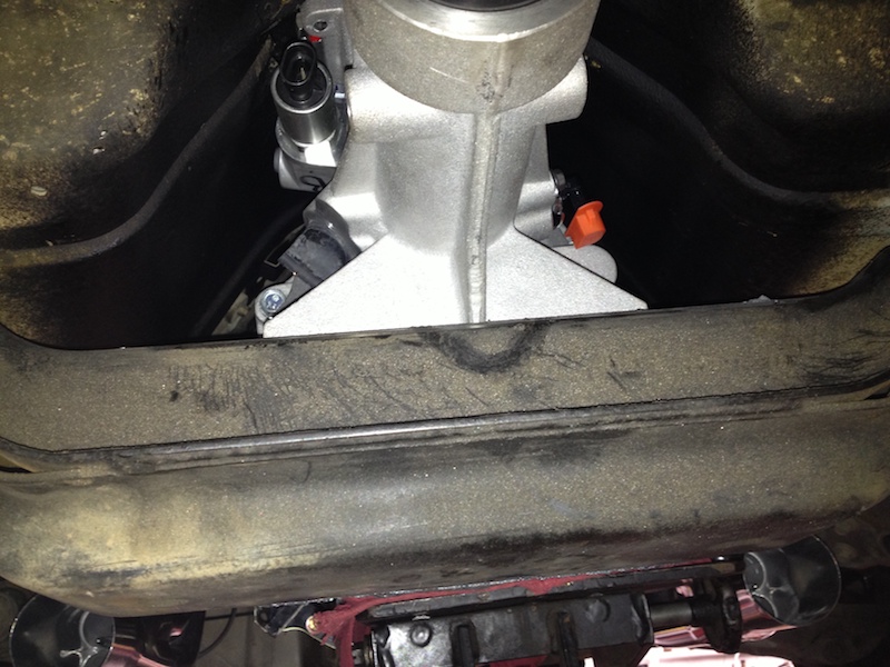
Here’s the piece welded in from the front of the car. We also had to trim the rear cross member for clearance with the seam on the tail shaft. We cut 1″ from left to right side for additional clearance or you can trim as you see marked below:
Once the cross member is installed on the car line up and mark the holes for the transmission mount. After removing the cross member we cut out holes on the bottom to gain access to the transmission mount nuts. After this we painted and installed it for the final time.


Remember a computer tune will be needed. Until you get wiring done you can keep the harness plugged into the range sensor and the vehicle will start.