Heinous Billet Upper and Lower Control Arm set for
1998 + Ford Crown Victoria, Grand Marquis
Lincoln Town Car & 03-04 Mercury Marauder
Tools needed:
- Floor jack and two jack stands
- Tire iron/sockets to remove lug nuts
- 15mm and 18mm sockets
- 21mm wrench
- Ratchet or impact/air ratchet
- Prybar or hydraulic spreader (like seen HERE )
- Torque wrench
- Loctite
- Energy Suspension (ENS) grease (Supplied)
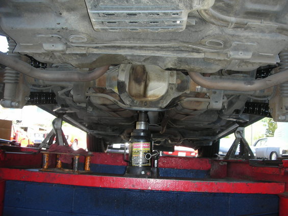
Note to Installer: All work should be performed on a suitable, level surface with the vehicle properly supported.
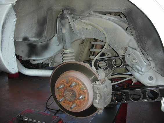
- It is necessary to raise the rear portion of the vehicle to replace the upper and lower control arms. Securely support the vehicle on each side approximately 7 inches forward of each lower control arm forward attachment point. The rear axle should be supported by a hydraulic jack at about the mid-point of its up/down travel range
- Both rear wheels should be removed for easier access to the control arm fasteners.
- The ADTR Heinous control arms are designed as direct replacements for the factory arms and the factory fasteners (or suitable equivalents) can be re-used.
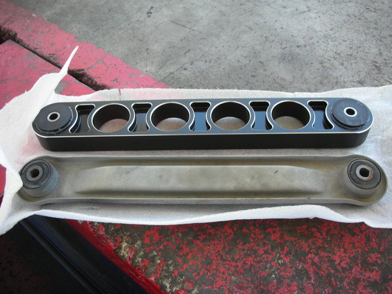
Upper arm comparison:
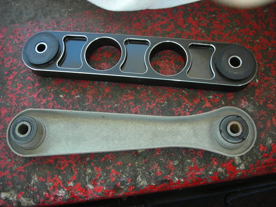
Lower arm comparison:
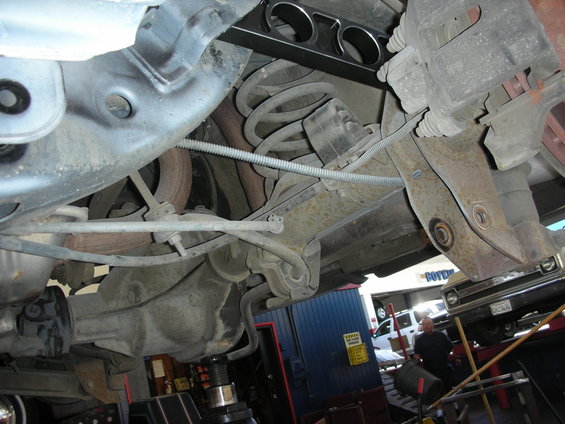
- The control arms should be changed one at a time to maintain the general alignment of the rear axle assembly during the replacement process. The fasteners for each new control arm should be left loose until all four control arms have been replaced.
- Install the lower control arms with the grease fittings facing down. The upper control arms can only be installed one way, as the mounting bolts are different sizes. The end with the smaller center pin attaches at the axle housing, and the end with the larger center pin attaches at the chassis with the (1) of the supplied washers on either side of the bushing. The washers sandwich the bushing. Use the ENS grease to stick the washers on the front bushing. I stuck the washer closest to the frame and put the arm in the pocket. Stick the bolt in to make sure the washer is aligned. Stick the other washer in and put the bolt in. Do not tighten it yet. The washers supplied are only needed on the upper control arm mounting to the frame pocket.
- The control arm fasteners should be torqued with the vehicle’s weight on the suspension to avoid creating an unwanted preload condition. The fasteners should be tightened to the following specifications to ensure no side-to-side movement of the control arms. Use extreme caution and keep jack stands under the vehicle while performing this step. Torque specs are as follows: Upper arm-to-frame bolt and flag nut 115 Nm (85 ft. lbs.) Upper arm-to-axle bolt and flag nut (smaller diameter bolt) 95 Nm (70 ft. lbs.) Lower arm-to-frame bolt and flag nut 115 Nm (85 ft. lbs.) Lower arm-to-axle nut and bolt 115 Nm (85 ft. lbs.) (We can’t stress how important it is to torque the rear control arms properly and make sure the rear suspension is loaded when you torque them. You may damage your bushings if they’re not torqued correctly!!!)
- The bushings should be lubricated using a quality chassis lube or polyurethane lubricant occasionally, using caution not to add too much lubricant which can cause deformation of the bushings. Do not pump grease through the grease fitting until you can see it oozing out. One small pump is all you need.
- The control arm fasteners should initially be checked for proper tightness after 50-100 miles of driving.
Enjoy and thank you very much for your purchase!