The following article was authored by Metroplex
===============================================
Ford 4.6L PI intake swap onto NPI 4.6L V8 (96-00 Panthers, 96-98 Mustang GTs, 96-97 T-birds/Cougars)
Directly applies to 96-00 Vics, can be useful for 96-98 GTs and 96-97 T-bird/Cougars)
As everyone knows, the Dupont Zytel Nylon (black plastic) intake manifolds used on Ford Modular engines have a tendency to leak coolant through the front coolant crossover port. In fact, there is a class action lawsuit regarding this issue but unfortunately the settlement leaves many people high and dry. This article presents an alternative solution to buying an expensive NPI intake manifold. On pre-01 Panthers, 96-98 Mustang GTs, and 96-97 T-bird/Cougars, you can opt to get a direct NPI replacement intake or live dangerously by getting a PI intake manifold as a replacement.
Why get a PI intake instead? For one, you can grab 10-15 ponies at the rear wheels with the use of a PI intake and you’ll solve the coolant problem all at the same time!
*NPI = Non-Performance/Power Improved (pre-01 Panthers, pre-99 GTs, pre-99/00 Trucks/Vans)
* PI = Performance/Power Improved (01-up Panthers, 99-up GTs, 99/00-up trucks/vans)
These are designations used by Ford enthusiasts to describe the cylinder head, camshaft, and intake manifold designs used on Ford 4.6/5.4/6.8 Modular Engines.
Parts Needed:
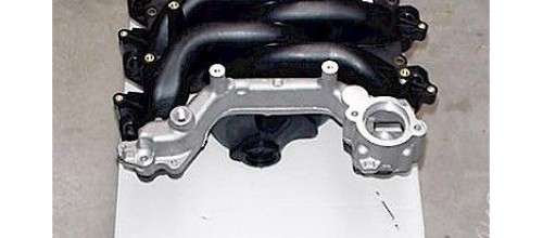
- Ford Racing PI Intake manifold*
- PI Intake manifold gaskets (x2)*
- PI coolant tube*
- 180F T-stat*
- T-stat O-ring*
- PI Coolant nipple*
- Optional: PI Intake alternator bracket**
- Optional: new o-rings for the fuel injectors
- Optional: water pump o-ring
- Optional: T-stat housing bolts
- Optional: Thermostat Housing
(*Included with ADTR PI intake swap kit)
(**You may need to re-use your stock bracket and drill holes for the alternator. The 2000 Vics use the same alternator as 2001-up Vics, so a 2001-up bracket is a direct bolt-on).

Note that in the diagram, there is no metal part covering the fuel hose. I found that the PI intake alternator bracket:1W7Z-10153-CA, works with the 4G civilian alternator and aluminum crossover (note: NPI and PI aluminum crossover are the SAME). But it sort of crams down the fuel hose against the intake runner and heats up the fuel in the hose through conducted heat in the bracket. Just cut the bracket so you retain the 4 bolt holes as in the diagram.
Materials Needed:
- Permatex Ultra Copper RTV
- Dielectric Silicone Grease
- Anti-Seize
- Anti-freeze
- Distilled water
- Sharpie markers (for labeling)
- Ziploc or sandwich bags (for holding bolts, etc)
- 3/8″ wire loom (for protecting fuel lines, vacuum lines, etc)
- High-Temperature exhaust paint or epoxy paint
Tools Required:
- Special A/C and Fuel Spring Lock tools
- Assorted Std Depth Metric sockets: namely 10mm, 13mm, 15mm
- Assorted Deep well Metric sockets
- 1/4″ drive ratchet w/ extension bar
- 3/8″ drive ratchet w/ extension bar
- 3/8″ drive in-lb torque wrench
- 3/8″ drive ft-lb torque wrench
- Slotted and Phillips Screwdrivers
- Slip-joint pliers
- Strap Wrench (for removing water pump pulley)
- Hammer
- Reciprocating saw w/ metal cutting blade
- Grinder with grinding stone and/or sandpaper rolls
- Razor Blade or high quality gasket scraper
- Vacuum cleaner
- 1/2″ short extension bar*
(*Pre-00 Vics only)
Some 98-00 Vics have the PI coolant nipple already installed at the factory, while others still retain the longer NPI coolant nipple. As far as I can tell, it’s a crap shoot for what’s included on your 98-00 Crown Vic. 96-97 Mustang GT owners have indicated they all had NPI coolant nipples while SOME 98 Mustang GT owners reported the PI coolant nipple pre-installed at the factory. The easiest way to tell what nipple is installed is by looking at the tube to nipple seal when the intake manifold is removed. If there is a noticeable gap between the flared lip of the coolant tube and the edge of the nipple/block, then you have the shorter PI nipple. At this point you do not have to remove the water pump! HOWEVER, if the coolant tube is SNUG against the edge of the nipple/block (there is no gap), you will need to remove the water pump to remove the NPI nipple and replace with the PI nipple. My 2000 Vic came with the PI nipple pre-installed but I drove it out like a mindless zombie with a 1 track mind.The NPI coolant nipples are made of a flimsy sheet metal so if you try whacking it with a hammer, you can easily deform it. The PI nipples are made of a tough cast material.
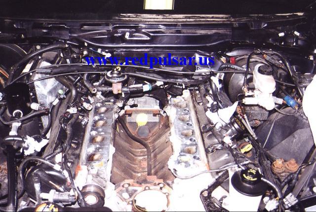
Click on the thumbnails to enlarge the photographs!

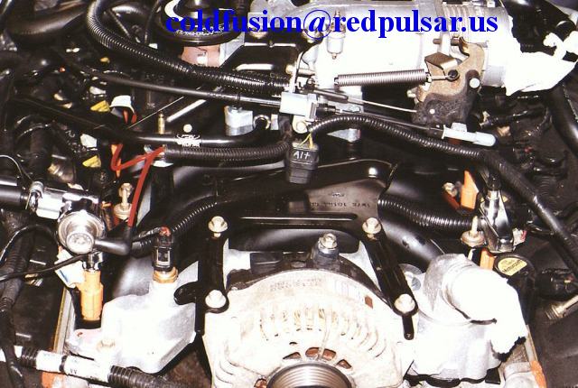
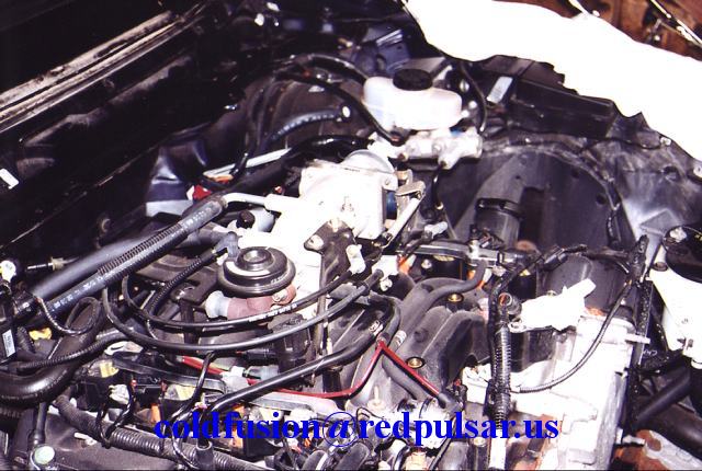
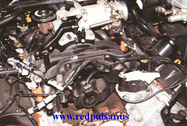
Pictures of assembled components


Pictures of components prior to PI intake swap and/or in stages of various disassembly.
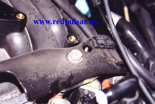
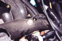
Crash Bracket
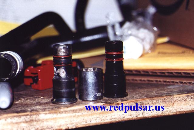
From left to right: New PI tube, old PI nipple, new PI nipple vs old PI nipple (same) and 15mm socket posing for a shot


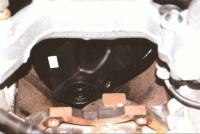
The water pump removed from the vehicle, this is a PW-386 used on 99-01 GT/Cobras.
Left: The rear bracket that is connected to the old coolant tube.Note: the sensor attached to the old coolant tube bracket is the EGR Differential Pressure Feedback Valve (aka transducer)


Thermostat Housing Comparison:

Original 1996-style housing used on all-nylon intake manifolds. Notice the areas indicated by the arrows.


New RH-151 housing designed for aluminum water cross-overs. The major differences are noted in the clearance between the alternator and the housing flange, as well as an extra piece of the housing that covers the port on the intake manifold. The old style housing has much larger mounting holes designed for brass inserts on the all-nylon intake. It is recommended that you purchase a new housing for your aluminum water crossover intake (it may be included in replacement kits though, so check before you buy).
Procedure:
Let the engine cool down overnight (to make sure engine block is cold, fuel pressure is at a minimum, etc)
- Remove the front end accessory drive belt. Disconnect negative terminal on battery, set parking brake. Drain all of the coolant; catch the coolant and recycle/dispose of it properly. Jacking/lifting the vehicle is not necessary.
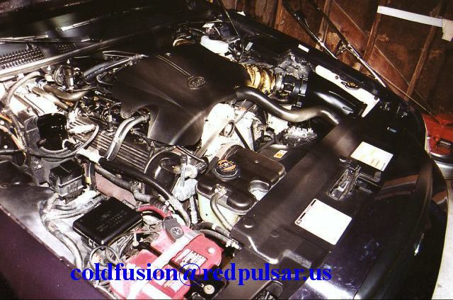
- Remove the engine cover shield from the plenum (use a 1/4″ drive nut driver or 1/4″ ratchet without a socket). Remove the radiator sight shield. Use compressed air to blow out debris/dirt from the surrounding area of the engine. Get rid of the crud!
- Label all electrical connectors and make notes on what goes where.
- Remove the air intake zip tube, it’ll be easier if you disconnected the MAF sensor harness, IAT harness, and pulled the air lid along with the zip tube as 1 piece. Make sure you disconnect the IAC (Idle Air Bypass tube) and crankcase breather tubes from the zip tube.
- Disconnect the TPS (Throttle Position Sensor) harness and the IAC harness.
- Disconnect all injector plugs and coil plugs (for 98-00 Vics), or spark plug wires (96-97 Crown Vics). Remove the coil packs on 98-00 Vics. Use compressed air to blow out the spark plug wells.
- Disconnect fuel lines using the special spring coupler tools. Use a catch can or suitable container to catch all of the dripping fuel. SAFETY WARNING: There may be a lot of fuel pressure so wear safety goggles, keep open flames and sparks AWAY from the fuel. Exercise extreme caution when dealing with gasoline.
- Remove the upper coolant hose and block the radiator and t-stat housing orifices using rags, Ziploc bags, etc
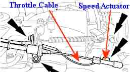
- Remove the brackets for the throttle cable and speed control cable and disconnect the cables from the throttle body as well. To disconnect the throttle cable from the TB (Throttle Body), open up the throttle and gently pull the cable downward out of the track and slide the cylinder away from the bracket. To disconnect the speed control cable, gently pry up on the plastic clip (it clips into a little snub on the bracket). Remember, if it’s not coming out, do NOT force it! Secure the cables away from the work area.
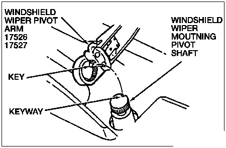
- Remove the windshield wiper arms, make sure you don’t lose the little keyway tabs that align the wiper arms to the shaft (little black squares) by bending them upwards at the joint and pulling the tabs out with a flat screwdriver and releasing them so they lock open].
- Remove the windshield wiper cowl and assembly. Start by removing the Phillips screws and cut off the two Christmas tree plugs. Disconnect the windshield wiper fluid hoses.
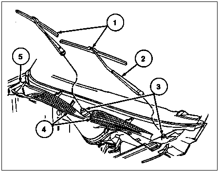
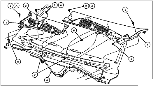
- Remove the two nuts for the evaporative emission canister purge valve; remove the bolts holding down the motor assembly and lift. Make sure to disconnect the motor harness and wiper fluid hose before removing the entire assembly.
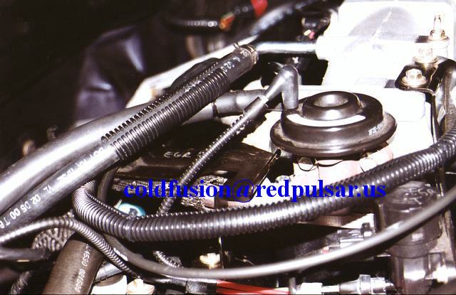
- Remove all the vacuum connections and disconnect the PCV valve. There aren’t many vacuum hoses and they’re all ‘pre-formed’ to fit properly so you can’t really screw it up. But label everything if possible. The sensor that sits close to the EGR that has 2 vacuum ports + a harness is the EGR vacuum regulator solenoid.
- Remove the EGR bolts. You do not need to remove the EGR tube. The alternator is removed so the intake can slide out.
- Remove the alternator bracket and alternator. Make sure you disconnect the voltage regulator harness and main power lead from the alternator. The alternator sits on two bolts that go into the block and have some minor support from 2 bolts that attach to the bracket. With the alternator out of the way, you can slide the intake out.
- Remove the upper intake elbow/plenum. There are FIVE bolts, 4 that are clearly visible and one that is a support. It’s found on a little leg that extends from the plenum body. Remove the gasket as well.
- Remove the LH crash bracket. It will be held by a large and LONG bolt. Use a 15mm socket. The crash bracket is also held by a 10 or 13mm nut and stud on the back of the LH cylinder head. Remove the nut first, and then find a bolt that holds the bracket. With that bolt removed, you can slide the bracket out of the way to remove the stud that is holding down the crash bracket. Remove the crash bracket.
- Remove the thermostat housing bolts as well as the O-ring and thermostat.
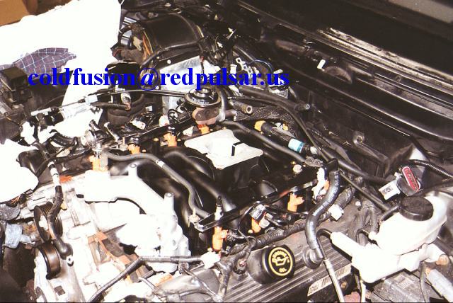
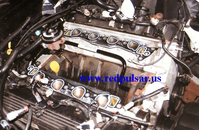
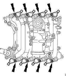
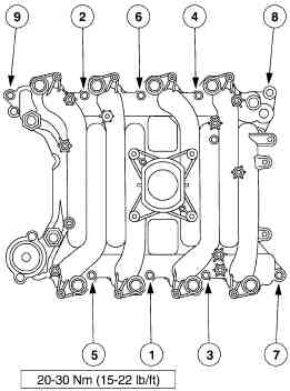
- Verify that all obstructions to the intake manifold have been removed, and proceed to remove all 8 bolts. A large wiring harness may be clipped into the RH rear of the intake manifold via a Christmas tree plug. There will be 5 bolts on the RH side, 3 bolts (not including the long crash bracket bolt) on the LH side, and the 2 t-stat housing bolts.
- Remove the intake manifold by sliding it out forward (the alternator IS out of the way, right?).
- Discard the intake manifold gaskets or re-use them if they’re in good shape.
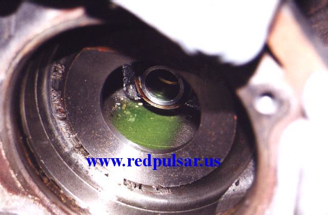
- See if you have an NPI coolant nipple or PI coolant nipple. Look for a noticeable gap between the coolant tube and the chamfered edge of the tube. If there is no gap and the tube runs almost seamlessly into the block], you have an NPI nipple and you need to follow the next few steps. If there is a rather large gap between the tube and the edge of the nipple, you have a PI nipple and can disregard the swap unless your stock nipple is leaking and/or damaged.
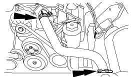
********Follow steps A-K only if you have to change the coolant nipple***********- Remove the water pump pulley by using the strap wrench to hold it still.Loosen and remove the bolts, and remove the pulley. If it does not come out, gently pry against the sides of it using a screwdriver.
- Remove the water pump bolts, being careful not to remove one of the front cover bolts.
- Use a screwdriver and pry the LH (driver) side tab on the water pump. There will be a notch in the cast iron block and a small tab on the body of the pump. Stick a large bar or screwdriver behind the tab and push the handle towards the intake manifold to ]lift] the water pump body. Once you see a small gap, tap in the water pump housing using a hammer (lightly tap!!!) and socket. Repeat this procedure until the pump is ]loose]. Once it is loose, make sure it’s fully seated, grip firmly and pull. Some coolant will gush out, so get ready.
- Clean the water pump O-ring sealing area.
- Find a socket that barely fits over the nipple head (the part that has 2 o-rings), it should be a 15mm standard depth socket. You want to find a socket that snugly fits over the nipple head so when you use a hammer, it does not deform the nipple. Slide the socket over the nipple so that it stays there.
- Gently tap on the socket with a large hammer. Gentle and even taps will drive out the nipple in less than 20 seconds.
- Clean the bore, and apply a thin layer of RTV on the new PI nipple.
- Seat the nipple evenly in the bore.
- Use the BACK end of a 1/2″ extension bar and gently tap in the nipple. Try to do this as evenly as possible because it is an interference fit.
- Once the outer lip of the nipple sits tightly against the block (there should be no gap), you’re set.
- ALWAYS install the nipple before installing the new PI coolant tube.******************
- It’s time to swap the coolant tubes. Make sure you use a nice protective polish/finish on the new tube to prevent possible rusting in the future. I used a layer of clearcoat on damaged parts of the new tube (it was scraped in a few spots during transit) and polished it with NuFinish.
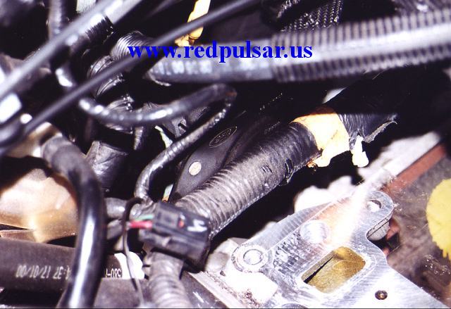
That’s the new PI coolant tube installed along with the new PI intake. - Find the large bracket on the rear of the RH cylinder head. There are 2 vacuum hoses attached to a sensor that has a wiring harness attached (EGR Transducer, or the Differential Feedback valve) Remove the wiring harness, and remove the nut that is holding that one side of the sensor. The other end clips onto the bracket.
- The grounding strap will be held down by a nut on a stud. This stud also holds down the coolant tube. Remove the nut that holds the ground strap and set the strap aside. Remove the stud from the coolant tube.
- Disconnect the heater core hose to the tube, and pull the tube from the nipple. Finagle the tube a little and remove from the vehicle.
- Lubricate the nipple o-rings with anti-freeze.
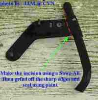
- In order to keep the bracket for the sensor and implement it on the new coolant tube, I used a Sawz-All to chop the stock bracket off at the NPI coolant tube keeping the bolt hole intact. I sanded and rounded off the edges, painted with exhaust paint, and bolted it with the new PI coolant tube. Torque the bolt and stud (not the ground strap nut) to 22 ft-lbs.
- Install the ground strap and bracket.
- Clean the gasket sealing surfaces on the cylinder heads and make sure the intake ports do not have debris. Vacuum if necessary.
- Transfer the ECT sensor(s) from the stock NPI intake over to the PI intake coolant crossover. Note, for pre-98 Panthers, 96-98 GTs, and 96-97 T-bird/Cougars, you will have to drill and tap an extra port on the crossover near the T-stat housing OR simply find an extra aluminum crossover from a NPI intake manifold and use that. The NPI and PI aluminum crossovers are interchangeable.For 98-00 Panthers, you’re good to go. Clean off the old thread sealant and apply new sealant or Teflon tape. Please note that the sensor has a tapered thread, do not use monster force to torque it down. Tighten it down enough so that nothing leaks. All 96-98 GTs and 96-97 T-birds/Cougars will have to drill/tap the extra hole or use a NPI aluminum crossover.
- Use a razor blade to clean off the EGR gaskets from the intake plenum and EGR valve.
- Now would be a good time to perform any TB or plenum upgrades.
- Take the PI gaskets and remove the locating nubs on the bottom side of the gaskets. Apply RTV around the coolant ports on the front and the rear of the gasket. Some say to put a small dab in the corner but I’ve always ran a bead all the way around the coolant port on both sides of the gasket.
- It takes 24 hours for RTV to fully cure at 60F+, so keep that in mind before you start up the vehicle. Slide the new intake over the gaskets making sure not to smear the RTV and finally drop it down.
- Install the crash bracket, making sure you hand tighten the big long bolt first to snug it down. Install the rear bracket bolt + stud + nut. Torque the bolt and stud to 22 ft-lb. Then start working the intake manifold bolts:
- Install the T-stat, O-ring, Housing, and then the bolts in that order. Apply anti-seize to the t-stat bolts and torque to 18 ft-lbs using the new included t-stat housing, or Motorcraft RH-151.
If you’re re-using your 1996 style housing, rotate the housing clockwise to the point where you can almost see the bolt hole (for 98-00 Vics, the stock T-stat housing isn’t exactly the best fit for the 01-up PI Intake, you’ll see why). The reason is the alternator, when fully seated, may contact the T-stat housing unless you rotate it a bit out of the way. This will not affect the o-ring seal since its still pushing down on the O-ring. - Here’s a good opportunity to change your IAC, EGR, TB, Spark Plugs, Fuel Injectors, Fuel Pressure regulator, and any other pertinent service items because they’re all easily removable at this point. However, this doesn’t mean go out and buy almost $500 worth of replacement parts.
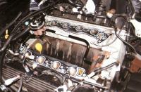
- Remove the fuel rails and injectors from the NPI intake and transfer them over to the PI intake. Remove any dirt from the injectors and o-rings, clean out the nozzle and filter by spraying with brake cleaner or suitable solvent (alcohol will work as well, just use stuff that you wouldn’t hesitate to put into your gas tank). Lubricate the O-rings with a thin coat of engine oil (dino 5W-30 will work). The fuel rail studs should be torqued to 79 in-lb.
- Install the ignition coil packs over the spark plugs, making sure you use plenty of dielectric silicone grease on the electrode for the spark plug.
- Slip the heater core hose over the coolant tube on the intake manifold and make sure the hose clamp is properly installed.
- Install the plenum assembly, and use a new IAC gasket if the IAC was removed, and use a new EGR gasket making sure the EGR gasket contact surfaces are CLEAN.
- Torque down the EGR bolts to 16 ft-lb, and the 5 plenum bolts to a max of 106 in-lb. In case I do not mention additional torque specs, anything that bolts onto the brass fittings in the Dupont Zytel Nylon intake manifold have a max torque of 106 in-lb, nothing more!! Anything that bolts onto the block will generally have a max of 22 ft-lb of torque (water pump bolts, alternator to block bolts, rear cylinder head bracket bolts, etc)
- Install the vacuum hoses, reconnect all electrical harnesses, and reconnect the throttle cable and speed control cables. To install the throttle cable, open up the throttle and slip the cylinder in making sure the cable goes into the track. Make sure the tranny dipstick is fully seated (it can pop out when working on the back part of the engine).
- Install the 2 bottom alternator bolts and seat the alternator against the block. Torque the bottom bolts to 22 ft-lb. Install the new alternator bracket or modified alternator bracket and torque the 4 top bolts to 106 in-lb in a cross pattern. Connect all wires/harnesses and install the belt.
- After waiting at least 12 hours (Ideally 24 hours) to let the RTV cure, fill about 1-2 gallons of 50/50 anti-freeze/distilled water. Have about 0.5-1 gallon ready when it bleeds out the air.
- Wait at least 1-2 hours and then start the engine and check for leaks (vacuum or fluid). Don’t make any plans to rev to 6000 RPM or go drag racing within 24 hours of this intake swap. Give it an easy week or so for the RTV to fully cure. If you think I’m BS’ing you on the cure time… I changed the gear oil on the E-250 about 8 months after we ordered it from Ford, and the Grey RTV Ford used to seal the cover was STILL wet/uncured. FYI I changed the gear oil from the factory fill dino SAE 90 to synthetic Redline 80W-140.
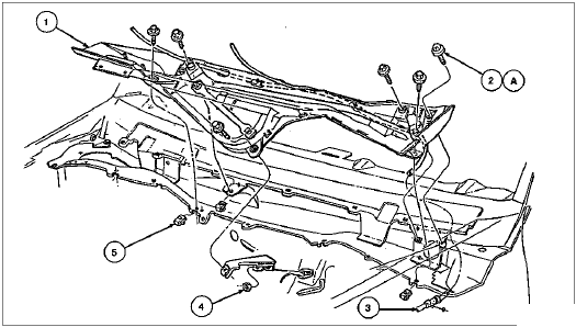
- After you have verified there are no vacuum or fluid leaks, re-install the wiper assembly, cowl, and wiper arms. Keep an eye on possible leaks from the temperature sensor threads. If it continues to leak, tighten it a tad more. If this does not solve the leak, remove the sensor when the engine is cold and reapply the sealant/Teflon tape.
- When you’re done, re-install the engine beauty shield, radiator sight shield, and you should be done.
